
Staging fuel nozzle

a technology gas turbine engine, which is applied in the direction of fuel injecting pump, machine/engine, light and heating apparatus, etc., can solve the problems of small effect and the stage of practical use of staging fuel nozzle, and achieve the effects of reducing the amount of nox generated, high speed and high degree of atomization

Active Publication Date: 2012-12-11
JAPAN AEROSPACE EXPLORATION AGENCY
View PDF10 Cites 24 Cited by
  • Summary
  • Abstract
  • Description
  • Claims
  • Application Information

AI Technical Summary

Benefits of technology

The present invention provides a staging fuel nozzle that improves combustion efficiency and reduces NOx in a medium or high load mode of the engine. The nozzle has a pilot fuel injection portion and a main fuel injection portion with at least two swirlers and a liquid film forming body around the pilot fuel injection portion. The fuel injection port is provided in an inner wall surface of the air flow channel located downstream of the swirlers, and a wall surface in the vicinity of the fuel injection port is made convex radially outward from an innermost surface of the innermost swirler. The nozzle also includes an effective opening area between the convex surface and the pre-filmer that is substantially equal to an effective opening area of the innermost swirler on the upstream thereof to minimize loss of speed and resistance to the swirling flow. The swirlers are combined to obtain a stable recirculation flow in the entire configuration, and a backward-facing step flame stabilizer can be provided to further increase combustion efficiency and reduce NOx formation.

Problems solved by technology

However, since the amount of air for improving the atomization of fuel is less than the total amount of air passing through the main air flow channel, the effect thereof is small.
As described hereinabove, in all of the above-described staging fuel nozzles, fuel is premixed with a sufficient amount of air and the mixture is subjected to lean combustion in the main burner to prevent the generation of high-temperature flame and reduce the amount of NOx that is generated in a large amount during high-temperature combustion, but these staging fuel nozzles have not yet reached the stage of practical use.

Method used


Image

  • Staging fuel nozzle
  • Staging fuel nozzle
  • Staging fuel nozzle

Examples


Embodiment Construction

[0033]The present invention will be described below in greater detail with reference to embodiments thereof illustrated by the appended drawings. The invention is not limited to these embodiments.

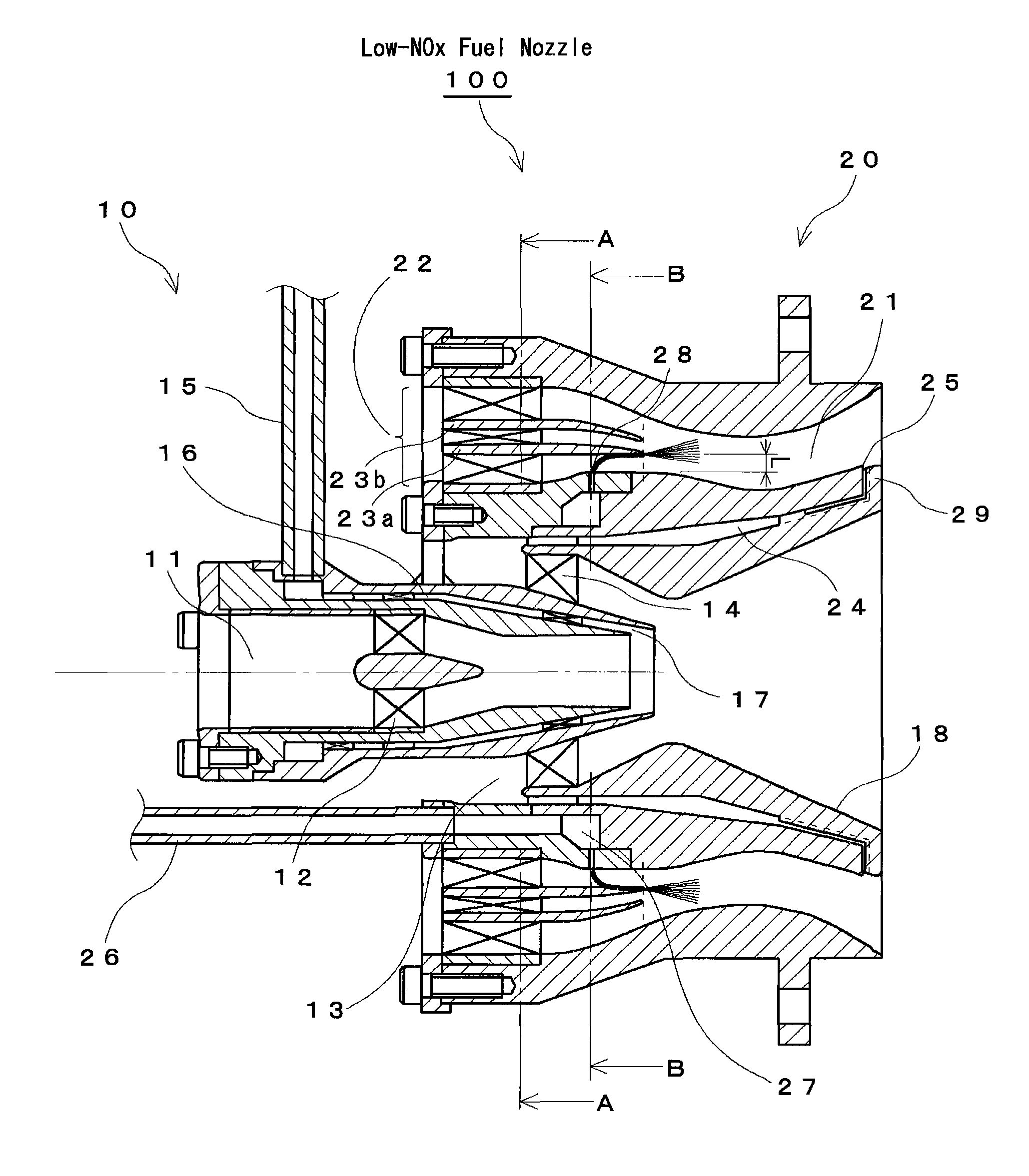
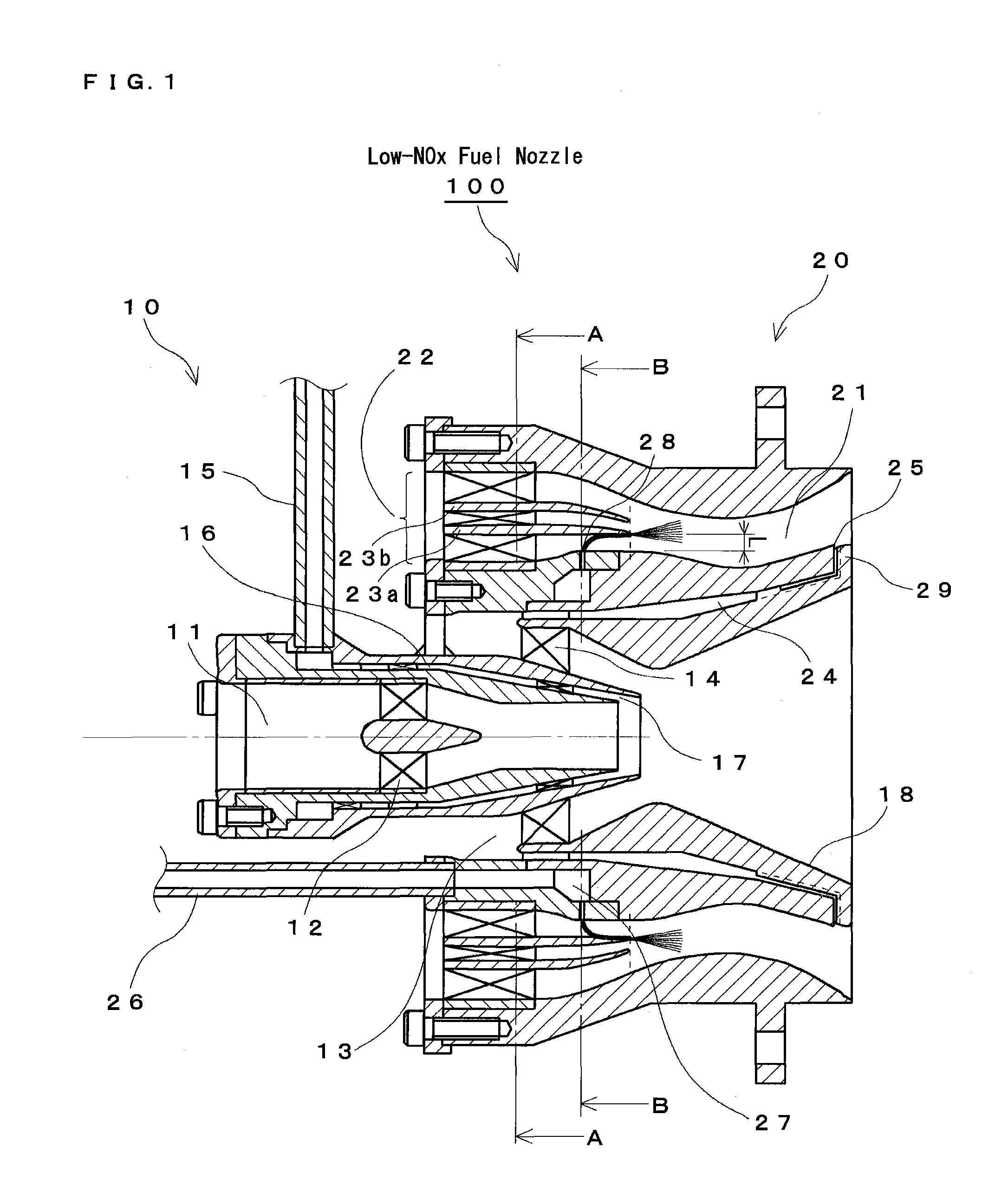
[0034]FIG. 1 is an explanatory drawing of a principal cross section illustrating a low-NOx fuel nozzle 100 in accordance with the present invention.

[0035]The low-NOx fuel nozzle 100 is configured by a pilot fuel injection portion 10 that atomizes fuel for diffusion combustion such as ignition and flame stabilization (referred to hereinbelow as “pilot”) and supplies the atomized fuel into a combustion chamber (not shown in the figure) and a main fuel injection portion 20 that is installed around the pilot fuel injection portion 10 and supplies a lean pre-mixture for lean premixed fuel (referred to hereinbelow as “main”) of main combustion into the combustion chamber. In order to increase the combustion efficiency in a low and medium load modes of the engine and reduce NOx emission in the hig...


PUM


Abstract

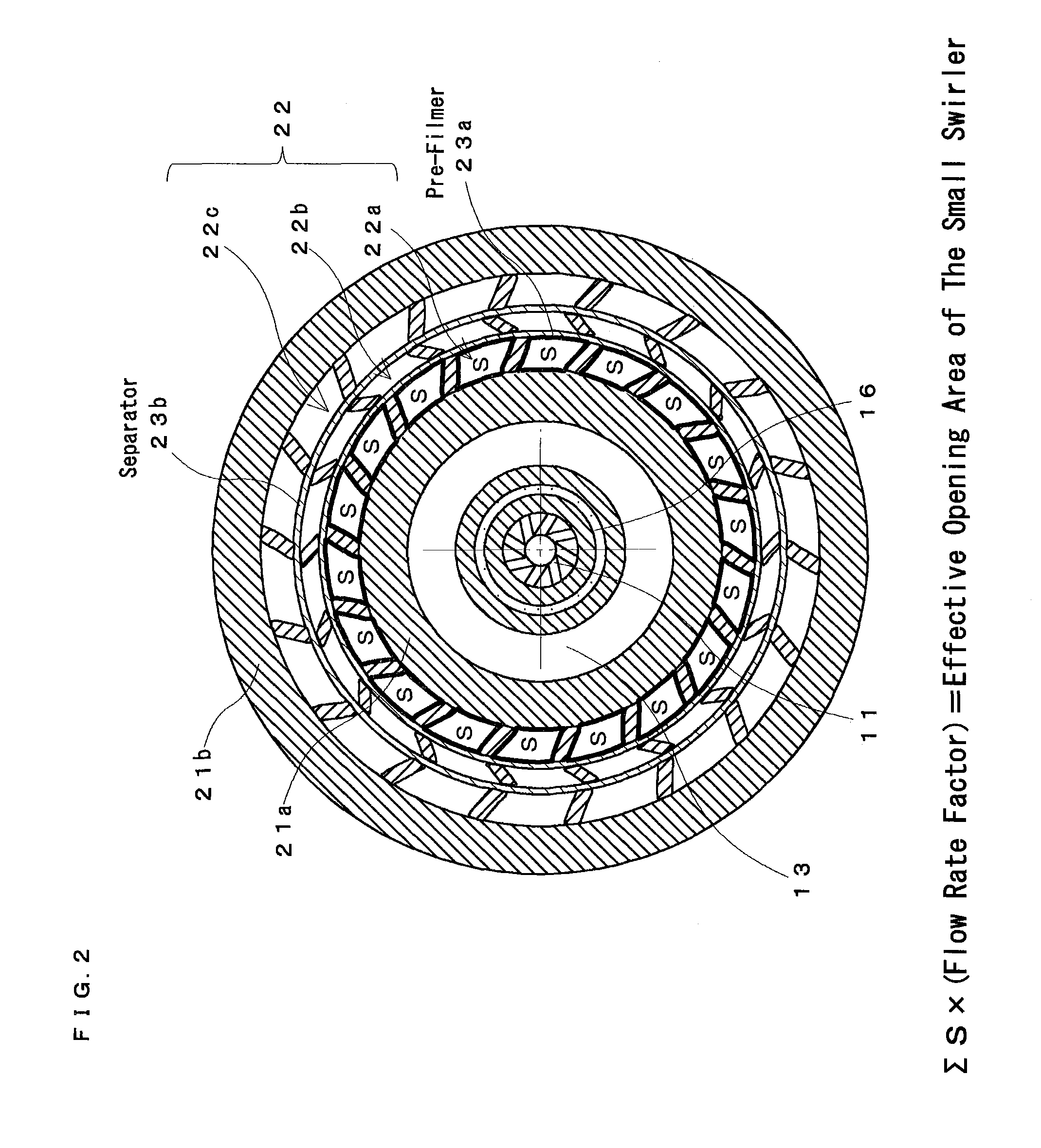
A main swirler of a triple annular configuration that is partitioned by a pre-filmer and a separator is installed in an inlet port of a main air flow channel. The vicinity of the inner wall of the main air flow channel provided with a main fuel injection port is bulged radially outward from the innermost surface (innermost surface of a small swirler) of a main swirler. Further, a distance from the main fuel injection port and the pre-filmer is set such that an effective opening area between the pre-filmer and “the inner wall of the main air flow channel provided with the main fuel injection port” is equal to an effective opening area of the small swirler. The swirling directions of the swirlers of the main swirler are “clockwise”-“counter-clockwise”-“clockwise” respectively along the radial outward direction when the swirling direction of the innermost swirler is taken as “clockwise”.

Description

BACKGROUND OF THE INVENTION[0001]1. Field of the Invention[0002]The present invention relates to a staging fuel nozzle of a gas turbine engine, and more particularly to a staging fuel nozzle that further increases combustion efficiency in a low or medium load mode of the engine and contributes to further reduction in NOx in a medium or high load mode of the engine.[0003]2. Description of Related Art[0004]A rich-lean combustion system based on diffusion combustion has been used in combustors of conventional jet engines for aircrafts. With such a combustion system, the correlation between the equivalent ratio φ and NOx generation amount has an almost symmetrical convex curved distribution with a center close to φ=1. Therefore, by conducting combustion in a rich state (fuel-rich state) with φ>1 in the upstream portion inside the combustor and then introducing air, it is possible to include combustion in a lean state (fuel-lean state) with φ<1 and avoid the combustion in the vicin...

Claims


Application Information

Patent Timeline
Patent Type & Authority Patents(United States)
IPC IPC(8): F02C1/00F02M61/00F02M61/02F23D11/10F02M63/00
CPCF23R3/343F23R3/286F23D2900/11101
Inventor YAMAMOTO, TAKESHISHIMODAIRA, KAZUOMATSUURA, KAZUAKIKUROSAWA, YOJIYOSHIDA, SEIJI
Owner JAPAN AEROSPACE EXPLORATION AGENCY
Learn More