Method for determining the position of the flux vector of a motor
a technology of flux vector and motor, which is applied in the direction of synchronous motor starters, dynamo-electric machines, electrical apparatus, etc., can solve the problems of low accuracy, difficult finalization, and relatively high cost of sensors, and achieve simple, precise and reliable control techniques.
- Summary
- Abstract
- Description
- Claims
- Application Information
AI Technical Summary
Benefits of technology
Problems solved by technology
Method used
Image
Examples
first embodiment
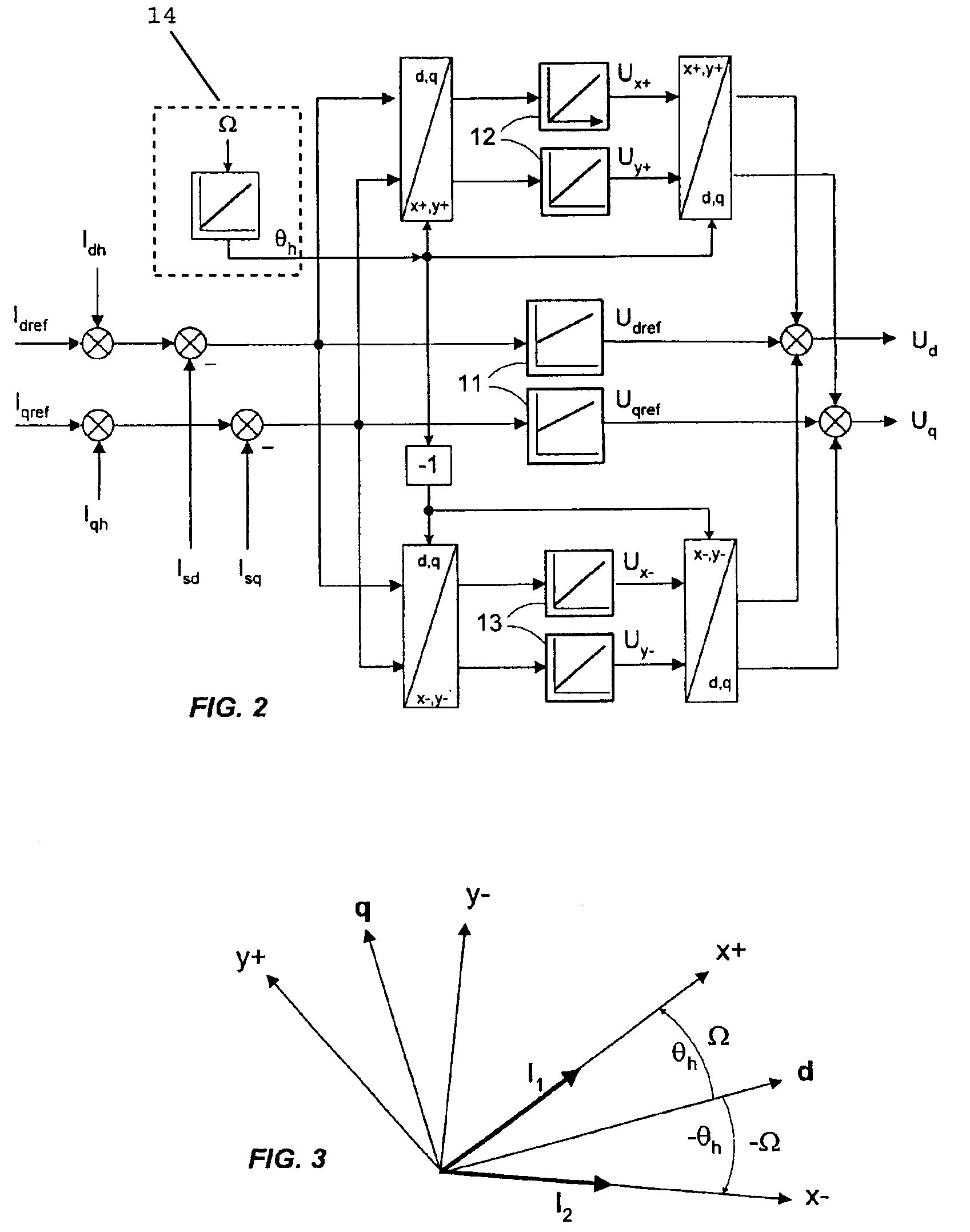
[0040]In a first embodiment, the current is injected with an amplitude I1 of the component in the reference frame x+, y+ which is equal to I and an amplitude I2 of the component in the reference frame x−, y− which is equal to zero. This mode is called harmonic current rotary injection. A current is therefore injected only by means of a current vector rotating at a positive injection frequency Ω. The current injection at a negative frequency is regulated to zero.
[0041]This then gives: Ih=I*ejΩt=I*cos (Ωt)+j*I*sin (Ωt)=Idh+j*Iqh.
[0042]In this first mode, the real portion Ux− (that is to say the x-axis component) of the second stator flux induced voltage U− is proportional to the error ε, according to the following formula:
[0043]Ux-=Re(U-)=(ΔL(Ω-2ω_)+3np24JΩφ_m2)Isin(2ɛ)
[0044]In which: ΔL represents the saliency inductance of which the value depends on the difference between the inductances Ld and Lq of the d and q axes of the motor M np represents the number of poles of th...
second embodiment
[0047]In a second embodiment, current injection is realized with amplitude I1 of the component in the reference frame x+, y+ which is equal to the amplitude I2 of the component in the reference frame x−, y−, that is I1=I2=I / 2. This embodiment is called harmonic current alternating injection. This case corresponds to the application of two components of the injected current Idh and lqh, with the amplitude Iqh equal to 0.
Ih=I / 2ejΩt+I / 2e−jΩt=I*cos (Ωt)+j*0=Idh+j*Iqh.
[0048]This embodiment is therefore equivalent to the application of an alternating current of frequency Ω only on the d axis (see FIG. 3). The resultant stator flux induced voltage UΣ is equal to:
UΣ=(U−−U+) / 2=UΣxj*UΣy=(Ux−−Ux+) / 2j*(Uy−−Uy+) / 2
[0049]In this second mode, the real portion of the second resultant stator flux induced voltage UΣ is proportional to the error ε, according to the following formula:
[0050]UΣx=Re(UΣ)=(ΩΔL+3np24JΩφ_m2)Isin(2ɛ)+3np216JΩΔL2I3sin(4ɛ)
[0051]An advantage of the second ...
PUM
 Abstract
Description
Claims
Application Information
 - R&D
- Intellectual Property
- Life Sciences
- Materials
- Tech Scout
- Unparalleled Data Quality
- Higher Quality Content
- 60% Fewer Hallucinations
Browse by: Latest US Patents, China's latest patents, Technical Efficacy Thesaurus, Application Domain, Technology Topic, Popular Technical Reports.
© 2025 PatSnap. All rights reserved.Legal|Privacy policy|Modern Slavery Act Transparency Statement|Sitemap|About US| Contact US: help@patsnap.com


