
Clad fiber capacitor and method of making same

a technology of clad fiber capacitors and capacitors, which is applied in the direction of wound capacitors, fixed capacitor details, fixed capacitors, etc., can solve the problems of low power density of current capacitors, inability to effectively operate or maintain operation at high temperatures, etc., and achieve high power density, high power density application

Active Publication Date: 2012-12-11
UT BATTELLE LLC
View PDF22 Cites 53 Cited by
  • Summary
  • Abstract
  • Description
  • Claims
  • Application Information

AI Technical Summary

Benefits of technology

The invention is a capacitor made using preforms that are built up from ductile, electrically conductive fibers and insulating cladding. The preforms are then insulated from each other using a ductile, electrically insulating spacer. The preforms can be assembled into a bundle and wound or woven into fabric or clothing to create a wearable energy storage unit. The diameter of the cladding, the length of the fiber, and the number density of the preforms determine the capacitance of the device. The preform structure can be pulled and shrunk to a smaller size, making it ideal for high temperature, high power density applications.

Problems solved by technology

Current capacitors generally have low power densities and cannot effectively operate or maintain operation at high temperatures.

Method used


Image

  • Clad fiber capacitor and method of making same
  • Clad fiber capacitor and method of making same
  • Clad fiber capacitor and method of making same

Examples


Embodiment Construction

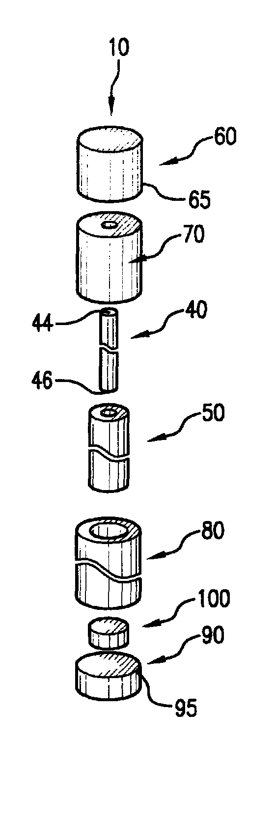
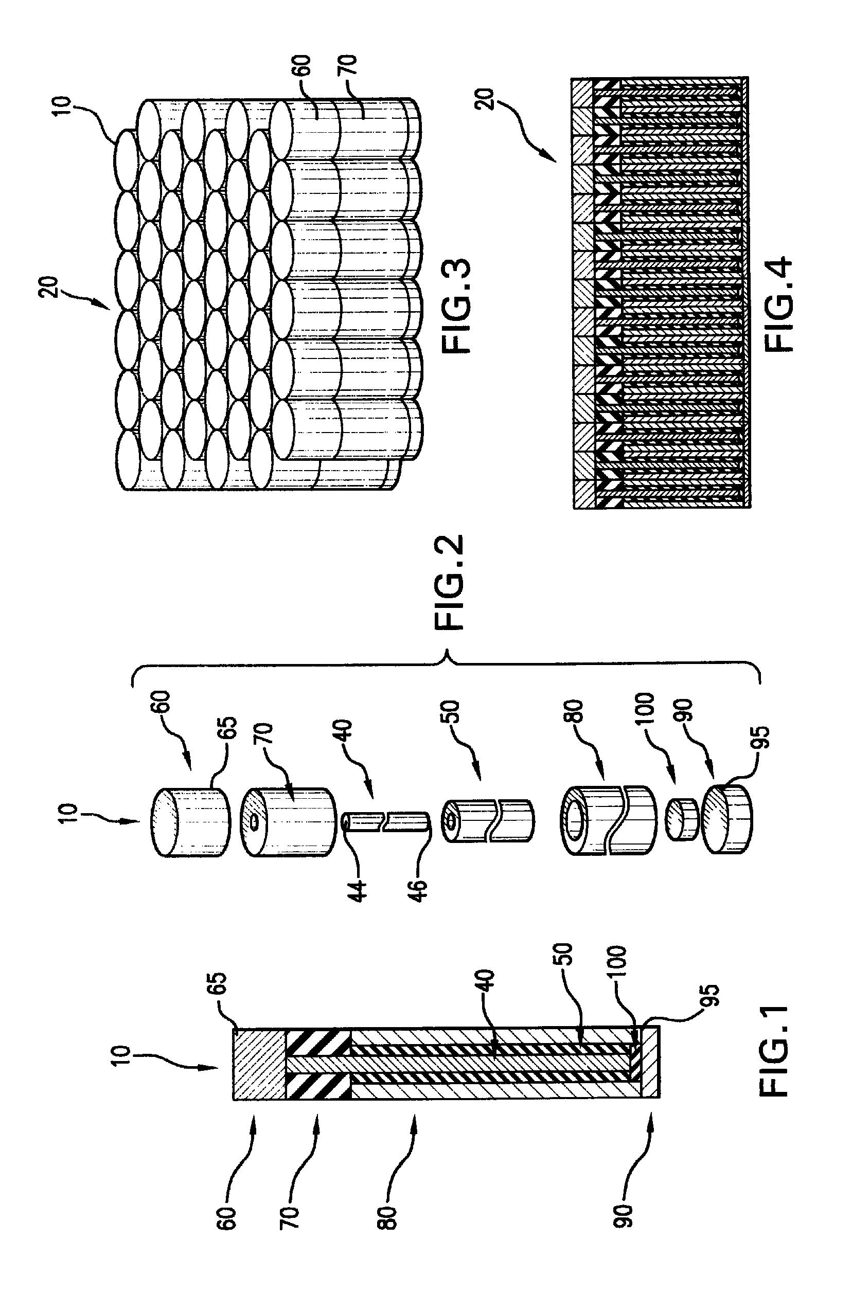
[0021]FIGS. 1-10 show various preferred embodiments of the invention. FIGS. 1 and 2 show a schematic cross-sectional view of a preform 10 according to one preferred embodiment of the invention and an exploded view of a preferred embodiment of the invention, respectively. The preforms 10 in the figures are shown schematically and, as such, the scale and relationship of the various components may be adjusted for clarity and discussion.

[0022]FIG. 1 shows the preform 10 for use in a capacitor device, as described in more detail below. As shown, the preform 10 preferably includes a ductile, electrically conductive fiber 40 having a first end 44 and a second end 46. As shown in the figures, the first end 44 is generally aligned toward the top of the figure and the second end 46 is generally aligned toward the bottom of the figure, however no particular fiber alignment is contemplated or required by the subject invention. According to a preferred embodiment of this invention, the electrica...


PUM

PropertyMeasurementUnit
diameteraaaaaaaaaa
diameteraaaaaaaaaa
heightaaaaaaaaaa

Abstract

A clad capacitor and method of manufacture includes assembling a preform comprising a ductile, electrically conductive fiber; a ductile, electrically insulating cladding positioned on the fiber; and a ductile, electrically conductive sleeve positioned over the cladding. One or more preforms are then bundled, heated and drawn along a longitudinal axis to decrease the diameter of the ductile components of the preform and fuse the preform into a unitized strand.

Description

GOVERNMENT RIGHTS[0001]This invention was made with government support under Contract No. DE-AC05-00OR22725 awarded by the U.S. Department of Energy. The government has certain rights in the invention.FIELD OF THE INVENTION[0002]The present invention relates to fabrication of high energy density capacitor devices using a drawn preform.BACKGROUND OF THE INVENTION[0003]Capacitors generally comprise two conductors, such as parallel metal plates, insulated from each other by a dielectric and are typically used to store electric energy. Current capacitors generally have low power densities and cannot effectively operate or maintain operation at high temperatures.[0004]As such, there exists a need for capacitors that are operable at high temperatures with sufficient capacity for use in specialized applications like defense, aerospace and transportation. Likewise, a need exists for a capacitor for use in such applications that is physically adaptable to various form factors.SUMMARY OF THE ...

Claims


Application Information

Patent Timeline
Patent Type & Authority Patents(United States)
IPC IPC(8): H01G4/30
CPCH01G4/105H01G4/28H01G4/06H01G4/38Y10T29/417Y10T29/435
Inventor TUNCER, ENIS
Owner UT BATTELLE LLC
Learn More