Method for fixing an electrical or an electronic component, particularly a printed-circuit board, in a housing and fixing element therefor

a technology of printed circuit boards and components, which is applied in the direction of electrical apparatus casings/cabinets/drawers, final product manufacturing, and connection of coupling devices, etc., can solve the problems of affecting the tolerance of printed circuit boards and housings, and affecting the quality of printed circuit boards

Inactive Publication Date: 2012-12-11
ROBERT BOSCH GMBH
View PDF17 Cites 59 Cited by
  • Summary
  • Abstract
  • Description
  • Claims
  • Application Information

AI Technical Summary

Benefits of technology

[0003]Example embodiment of the present invention provide a method, a fixing element and an electrical or an electronic component of the type mentioned at the outset, to the extent that a secure, firm and durable fixing of the component in the housing is possible without special tolerance requirements.
[0005]According to example embodiments of the present invention, at the interfaces between the electrical or the electronic component and the housing, that is, in the place where the clamping forces are transferred from the housing to the component, instead of having a direct transfer of the clamping forces, one should select an indirect transfer, via an elastically yielding intermediate member, that is fit in between the component and the housing, so as to compensate for tolerances or play that may possibly be present in the area of the clamping connection. Since the elastically yielding press-on part is able to be deformed more or less severely, in correspondence to the respective installment conditions, the tolerance requirements on the housing and on the component itself may be considerably reduced. Furthermore, the different thermal expansions of the component and the housing may be compensated for via the elastically yielding press-on part of the at least one fixing element. In addition, with the aid of the elastically yielding press-on part, the contact surface between the component and the housing is able to be enlarged, which, because of lower surface pressures, leads to a reduction in the mechanical stresses caused by the clamping connection, and thus to an extension in the service life of the component. In addition, if the material is selected suitably, the elastically yielding press-on part also acts as a damping member, which damps the transfer of vibrations from the housing to the component, and consequently ensures, at least partially, a decoupling of the component from the housing according to vibration technology.
[0006]The method according to example embodiments of the present invention provides that the fixing element is fastened on the component by soldering, especially if the latter is a printed-circuit board. This type of fastening has the advantage that the fixing element is able to be applied, using an already present placement system, in the same manner as other components that are to be mounted on the printed-circuit board, so that the printed-circuit board is able to be fitted with the fixing element(s) using only slight additional effort, in the course of its manufacture.
[0008]The press-on part of the fixing element is made up advantageously, at least in part, of an elastic plastic material, such as polytetrafluoroethylene (PTFE) or an elastomer, such as polyurethane foam or a thermoplastic elastomer (TPE). A rubber elastic material may also be used, however, such as ethylenepropylenediene rubber (EPDM) or a silicone, as long as this material is elastically yielding when a clamping force is applied, and is able to be applied without difficulty onto a suitable carrier of the fixing element.

Problems solved by technology

However, such connections are not free of disadvantages.
Whereas an adhesive connection is no longer detachable after manufacturing, and may additionally lead to damage of the printed-circuit board or of the components mounted on it because of the chemical substances contained in the adhesive, screwed connections and clip-on connections are detachable, to be sure, but they put high requirements on the tolerances of the printed-circuit board and the housing.
In addition, the mechanical stresses on the printed-circuit board may be very high in such a location.
In this way, additional contact measures between the electrical or electronic component and its housing become superfluous.

Method used


Image

  • Method for fixing an electrical or an electronic component, particularly a printed-circuit board, in a housing and fixing element therefor
  • Method for fixing an electrical or an electronic component, particularly a printed-circuit board, in a housing and fixing element therefor
  • Method for fixing an electrical or an electronic component, particularly a printed-circuit board, in a housing and fixing element therefor

Examples


Embodiment Construction

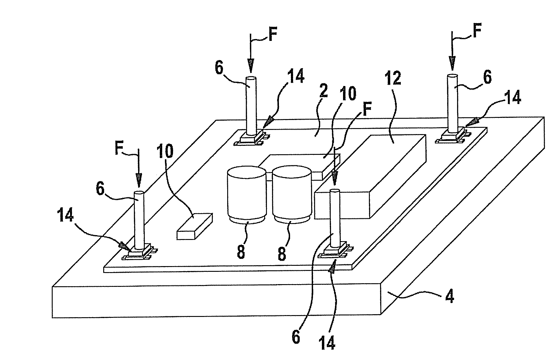
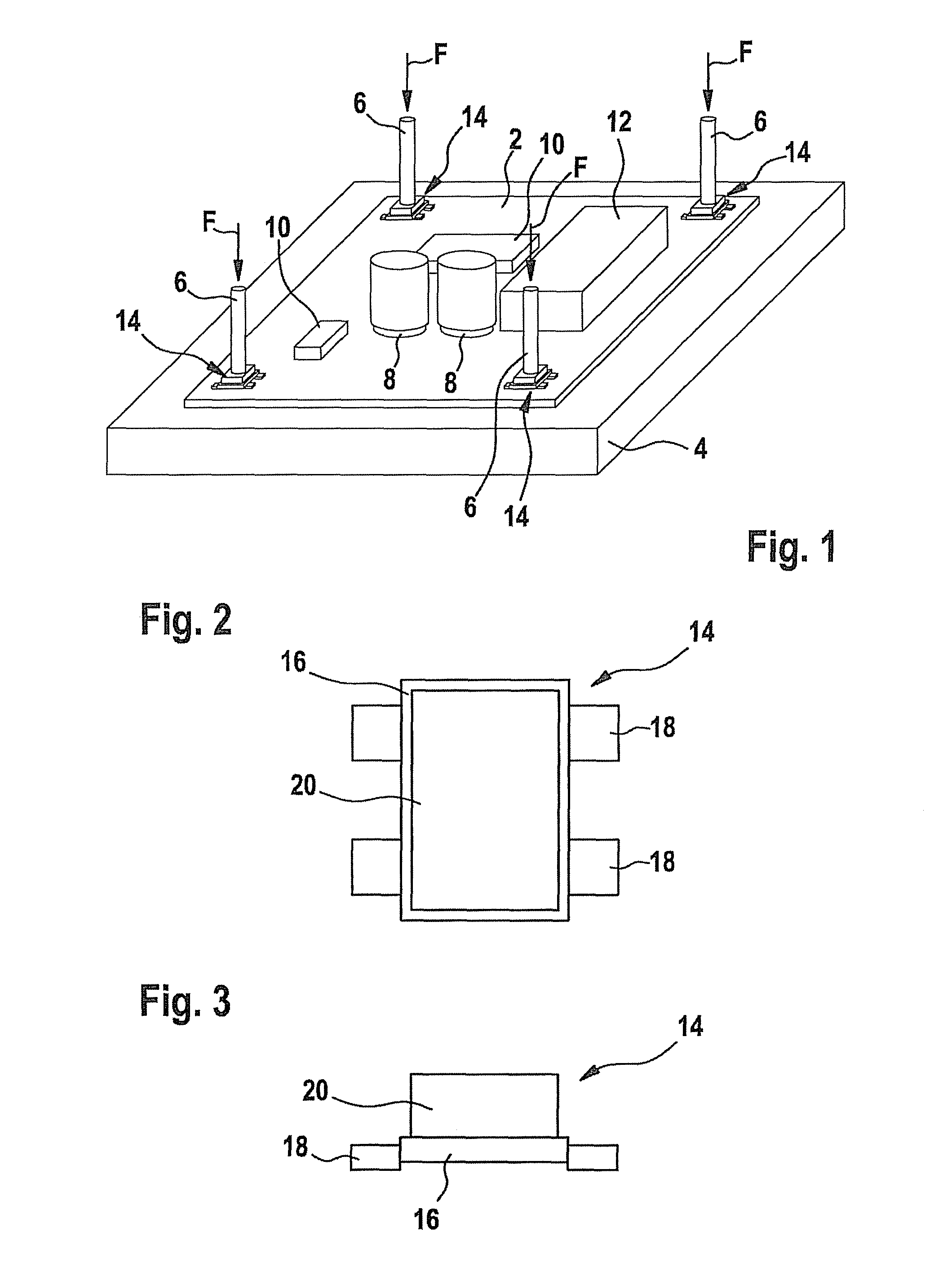
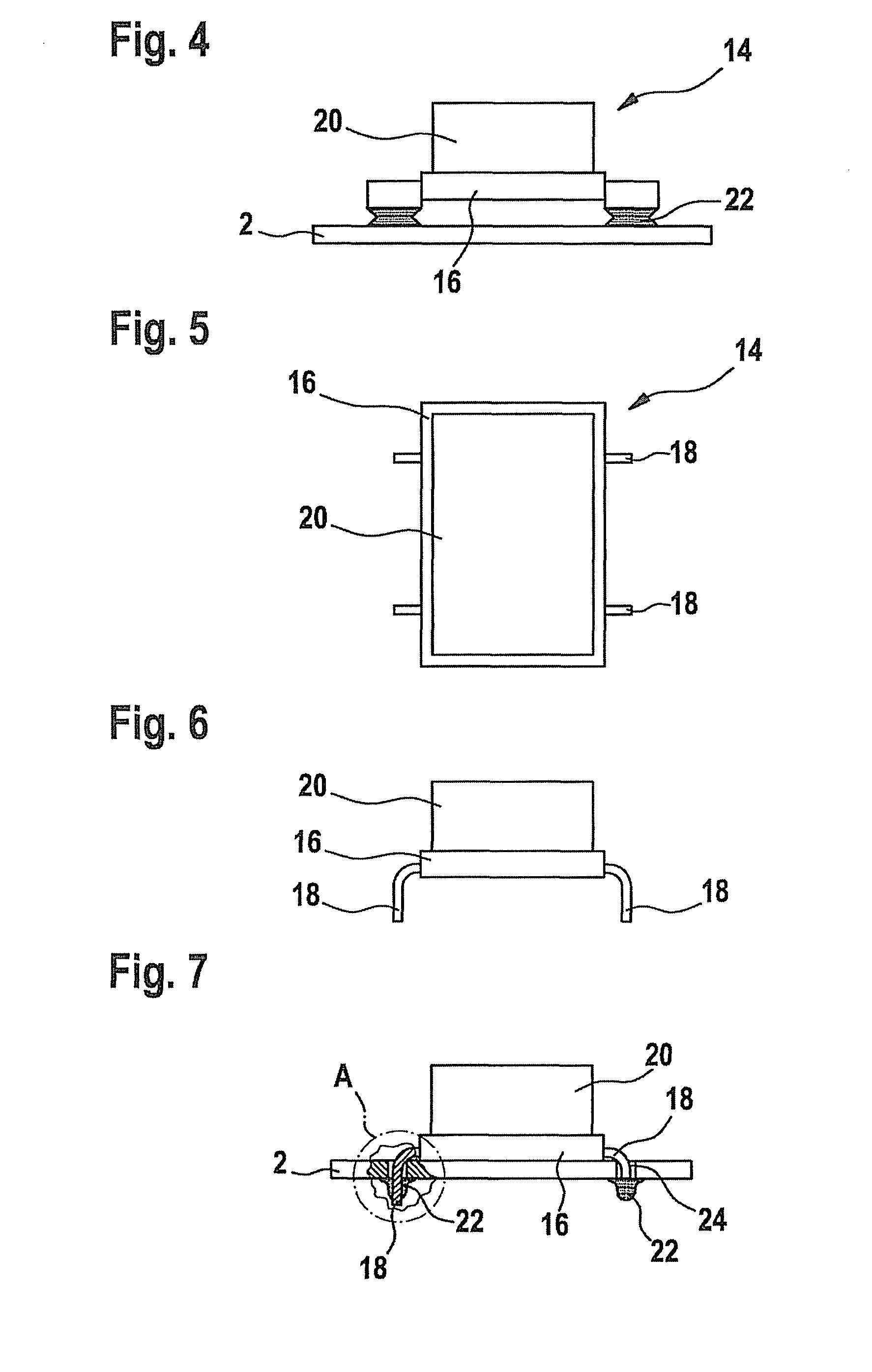
[0022]The printed-circuit board 2, shown best in a drawing in FIG. 1, is fixed in a housing a clamping connection, by pressing it on from above by its underside against a firm, even substratum 4, for instance, a floor of the housing. The pressing-on of printed-circuit board 2 against substratum 4 takes place with the aid of a plurality of cylindrical holding pins or similar extended housing projections 6, which project, for instance, above the lower side of the cover (not shown) of the housing, and, when the cover is closed, extend downwards into the vicinity of printed-circuit board 2, past a plurality of electronic components mounted on the face of printed-circuit board 2, such as capacitors 8, memory chips 10, processors 12 and the like, where they exert in each case a clamping force (arrows F) on a fixing element 14 that is rigidly mounted below each projection 6 on the face of printed-circuit board 2, in order to press fixing element 14, and via it, printed-circuit board 2, dow...


PUM

PropertyMeasurementUnit
elasticaaaaaaaaaa
electrically conductiveaaaaaaaaaa
adhesionaaaaaaaaaa

Abstract

In a method for fixing an electrical or an electronic component, particularly a printed-circuit board, in a housing used to accommodate the component, and a fixing element for fixing the component by clamping it in place, the component is fitted with at least one fixing element, which includes an elastically yielding press-on part which, during the clamping in place of the component in the housing, is brought to lie against a part of the housing and is pressed against it while being deformed.

Description

FIELD OF THE INVENTION[0001]The present invention relates to a method for fixing an electrical or an electronic component, particularly a printed-circuit board, in a housing used for accommodating the component, a fixing element for fixing an electrical or an electronic component in a housing by clamping it in place, and an electrical or an electronic component, particularly a printed-circuit board.BACKGROUND INFORMATION[0002]The most varied technical design approaches exist for fixing electrical or electronic components, particularly printed-circuit boards in a surrounding housing. The printed-circuit board may be firmly screwed or adhered into the housing, for example, or may be connected to the housing by clipping it on. However, such connections are not free of disadvantages. Whereas an adhesive connection is no longer detachable after manufacturing, and may additionally lead to damage of the printed-circuit board or of the components mounted on it because of the chemical substa...

Claims


Application Information

Patent Timeline
Patent Type & Authority Patents(United States)
IPC IPC(8): H05K5/00
CPCH05K1/18H05K1/181H05K7/142Y10T29/5327H05K2201/0133Y10T29/49954Y10T29/49947H05K2201/10393Y02P70/50
Inventor GEISSLER, ALEXANDERHENNEL, UDO
Owner ROBERT BOSCH GMBH
Why Eureka
Try Eureka