LED grow light

a grow light and led technology, applied in the field of led light, can solve the problems of not being very useful for plants, mcpcbs are relatively new technology, and typically cost three times or more compared to fr4 pcbs, and achieve the effect of reducing assembly cos

Active Publication Date: 2012-12-18
MODERN WOODWORKS
View PDF1 Cites 18 Cited by
  • Summary
  • Abstract
  • Description
  • Claims
  • Application Information

AI Technical Summary

Benefits of technology

[0015]3. High Brightness (HB) LEDs (two strings). Thermal vias are used to thermally connect the HB LEDs on one side of the PCB to the heat sink on the other side. In addition, the through hole and surface mounted technology (SMT) components are combined on the PCB to lower assembly cost.
[0016]The present invention significantly lowers the cost of manufacturing an LED light fixture by using:
[0020]The final assembly is faster and done at a lower cost since additional assembly and wiring for the LED driver circuits is not required and the overall design enables the device to be easily sealed from humidity.

Problems solved by technology

In addition, LEDs can be focused on the photo-synthetically active regions of the light spectrum, namely blue and red (400-500 nm and 600-700 nm respectively) without wasting energy on the green (500-600 nm) region which is not very useful to plants during the vegetative phase.
However, MCPCBs are relatively new technology and typically cost three times or more compared to FR4 PCBs (fiberglass based PCBs).
In addition, hole plating can not be accomplished with MCPCBs.
In this regard, it is difficult to integrate the power supply / LED driver circuit with high brightness (HB) LED on the same MCPCB.
Most HB LED light fixtures mount LEDs on an MCPCB then use a separate FR4 based PCB for the power supply / driver circuit resulting in higher assembly costs.

Method used


Image

  • LED grow light
  • LED grow light
  • LED grow light

Examples


Embodiment Construction

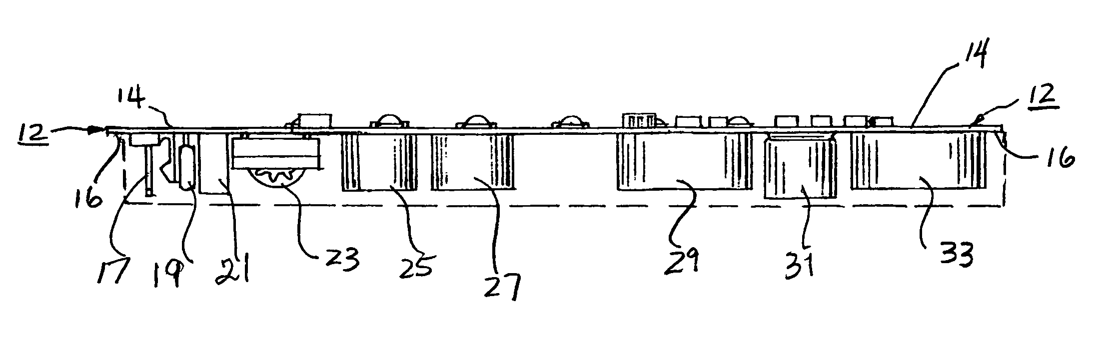
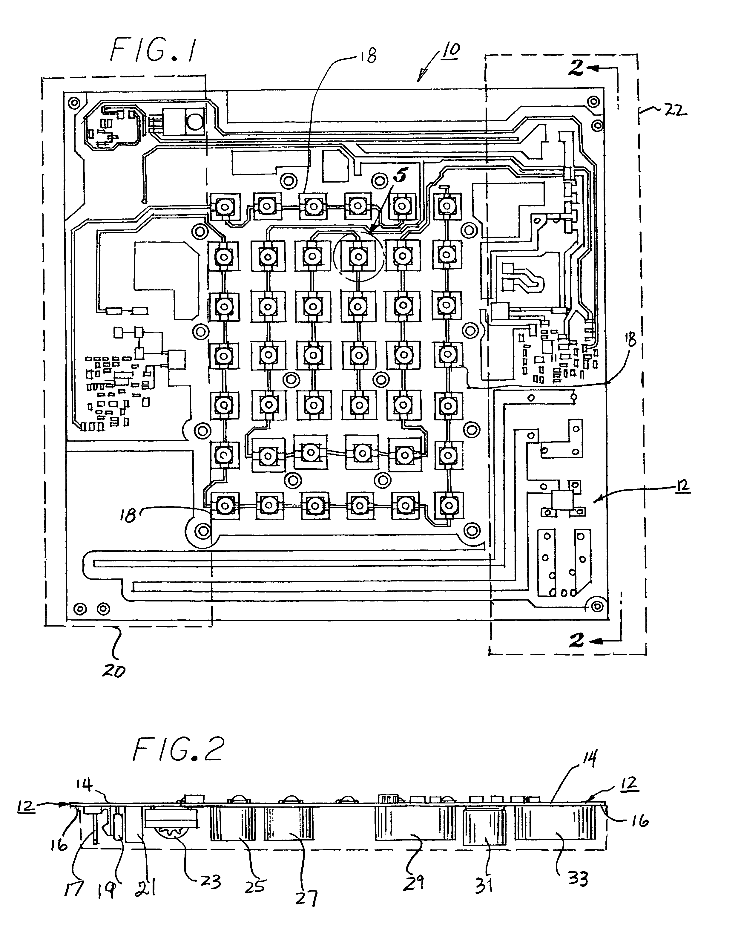
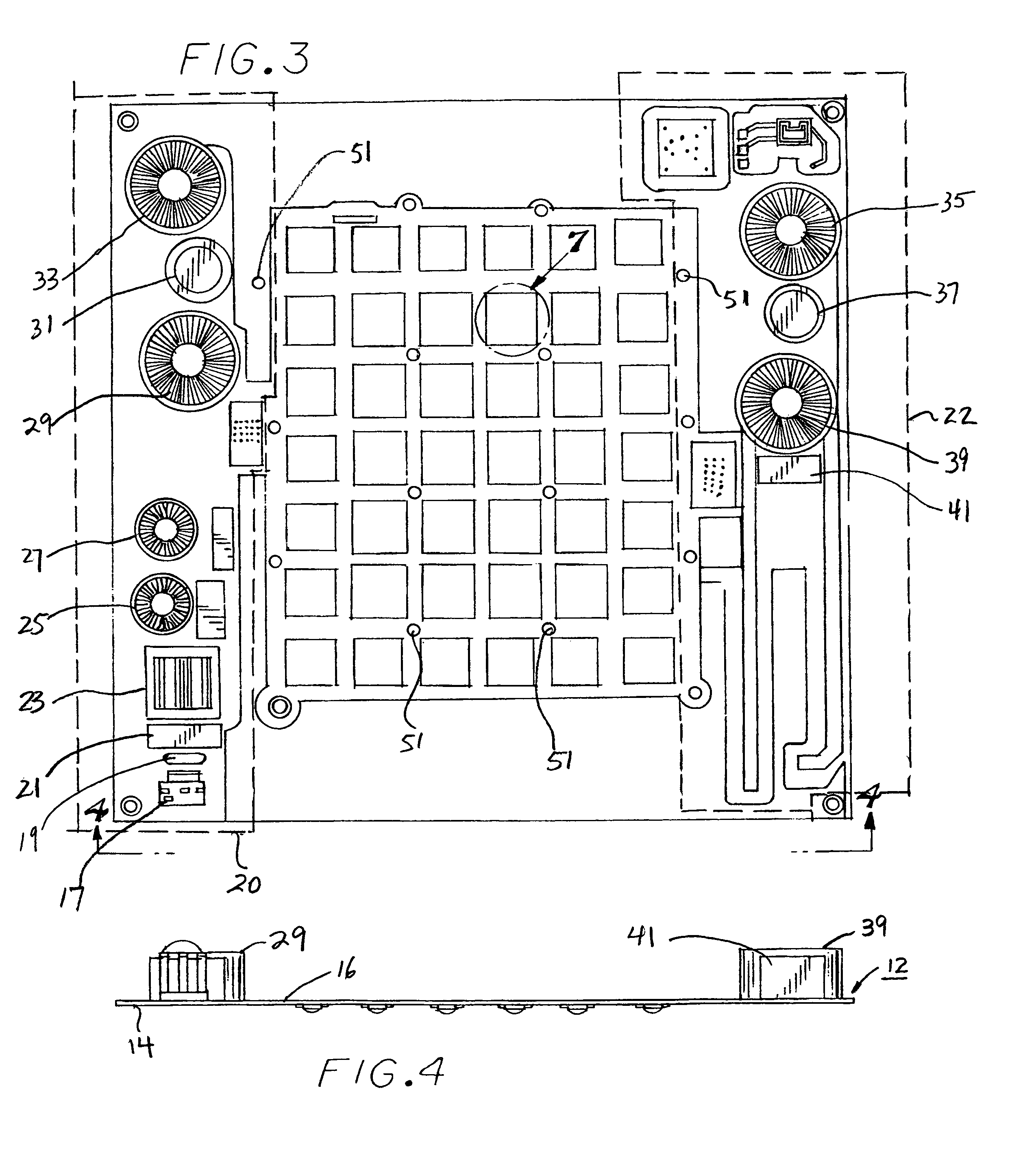
[0032]Referring now to FIGS. 1 and 2, a top view of the LED grow light fixture 10 of the present invention is illustrated. In accordance with the teachings of the invention, a single FR4 based two sided printed circuit board (PCB) 12 has a top layer 14 and bottom layer 16. A plurality of constant current LED emitter components 18 are mounted on layer 14 using conventional PCB component mounting processes, such as the surface mount technology (SMT) which allows SMT components to be more densely populated on a PCB. The LEDs generate radiation of five different wavelengths corresponding to the colors blue, deep blue, red, deep red and white. A pair of switching mode supplies 20 and 22 (preferably 75 W each) are formed on layer 14 of PCB 12 as illustrated. Since the total power of fixture 10 is 130 W, in order to maintain the proper dimensions of the, the design preferably is split such that each power supply drives half of the LEDs on the fixture. The LEDs are connected in series formi...


PUM


Abstract

A light system for growing plants indoors comprising a light source mounted on a single, two sided FR4 based PCB board.

Description

BACKGROUND OF THE INVENTION[0001]1. Field of the Invention[0002]The present invention provides a LED light utilized in the field of indoor horticulture lighting, the light comprising at least three LEDs each emitting light of a different frequency.[0003]2. Description of the Prior Art[0004]High intensity discharge (“HID”) lights have been used in indoor horticulture for many years. Specifically, there are two types of HID lights used for indoor growing: metal halide (MH) and high pressure sodium (HIPS) based systems. MH lights have a blue tint and are typically used during vegetative growth. HPS lights emit a yellowish / red tint used for the flowering portion of the grow process.[0005]The field of light emitting diodes (LED) is a rapidly advancing technology that has the promise to significantly reduce power consumption for general lighting as well as for indoor horticulture. Over the last five years, ever brighter and more efficient LED emitters in the 3-5 W range have been develope...

Claims


Application Information

Patent Timeline
Patent Type & Authority Patents(United States)
IPC IPC(8): F21V29/00
CPCA01G7/045F21V29/74F21Y2101/02A01G9/249F21Y2115/10Y02P60/14
Inventor MEKHTARIAN, GEORGE
Owner MODERN WOODWORKS
Why Eureka
Try Eureka