
Device and method for determining tissue thickness and creating cardiac ablation lesions

a tissue thickness and cardiac ablation technology, applied in medical science, surgery, diagnostics, etc., can solve the problems of cell death, intact structure, blockage of electrical pathways within the tissue,

Inactive Publication Date: 2012-12-18
MEDTRONIC INC
View PDF408 Cites 1244 Cited by
  • Summary
  • Abstract
  • Description
  • Claims
  • Application Information

AI Technical Summary

Benefits of technology

The invention is a tissue ablation system with a handle and an ablation head. The ablation head has two jaws and an ablative element. The system also includes a thickness measurement device that indicates the distance between the jaws, a force measurement device that indicates the force being applied by the jaws, and a strain measurement device that indicates the strain resulting in the tissue when a stress is applied. The invention also includes a method for assessing the transmurality of an ablation lesion and a method for ablating tissue. The technical effects of the invention include improved accuracy in ablation procedures and improved safety during surgical ablation procedures.

Problems solved by technology

With sufficiently high levels of electrical energy between the two electrodes, heat is generated which is sufficient to denature proteins within the tissue and cause cell death.
High levels of voltage can cut and remove tissue (i.e. electrosurgery), while lower levels will simply create sufficient heat to cause cell damage, but leave the structure intact and block electrical pathways within the tissue.
Non-transmural lesions may be capable of propagating a depolarization wave form, or action potential and may not be effective in treating an arrhythmia.
One challenge associated with ablation procedures relates to determining the proper energy to apply to the tissue and duration of application of that energy in order to achieve the desired transmurality.
However, such an approach requires an accurate assessment of tissue thickness, which may also present a challenge.
Such variability impacts the most effective treatment time and energy.
The design challenge with any ablation device, and in particular with a hemostat type device, is to create a lesion having consistent quality, in particular a continuous linear lesion when engaging in the Maze procedure.
Further, a challenge in the creation of such a device is to reduce the variability based upon the user such that a device may be used by various users with consistent results.

Method used


Image

  • Device and method for determining tissue thickness and creating cardiac ablation lesions
  • Device and method for determining tissue thickness and creating cardiac ablation lesions
  • Device and method for determining tissue thickness and creating cardiac ablation lesions

Examples


Embodiment Construction

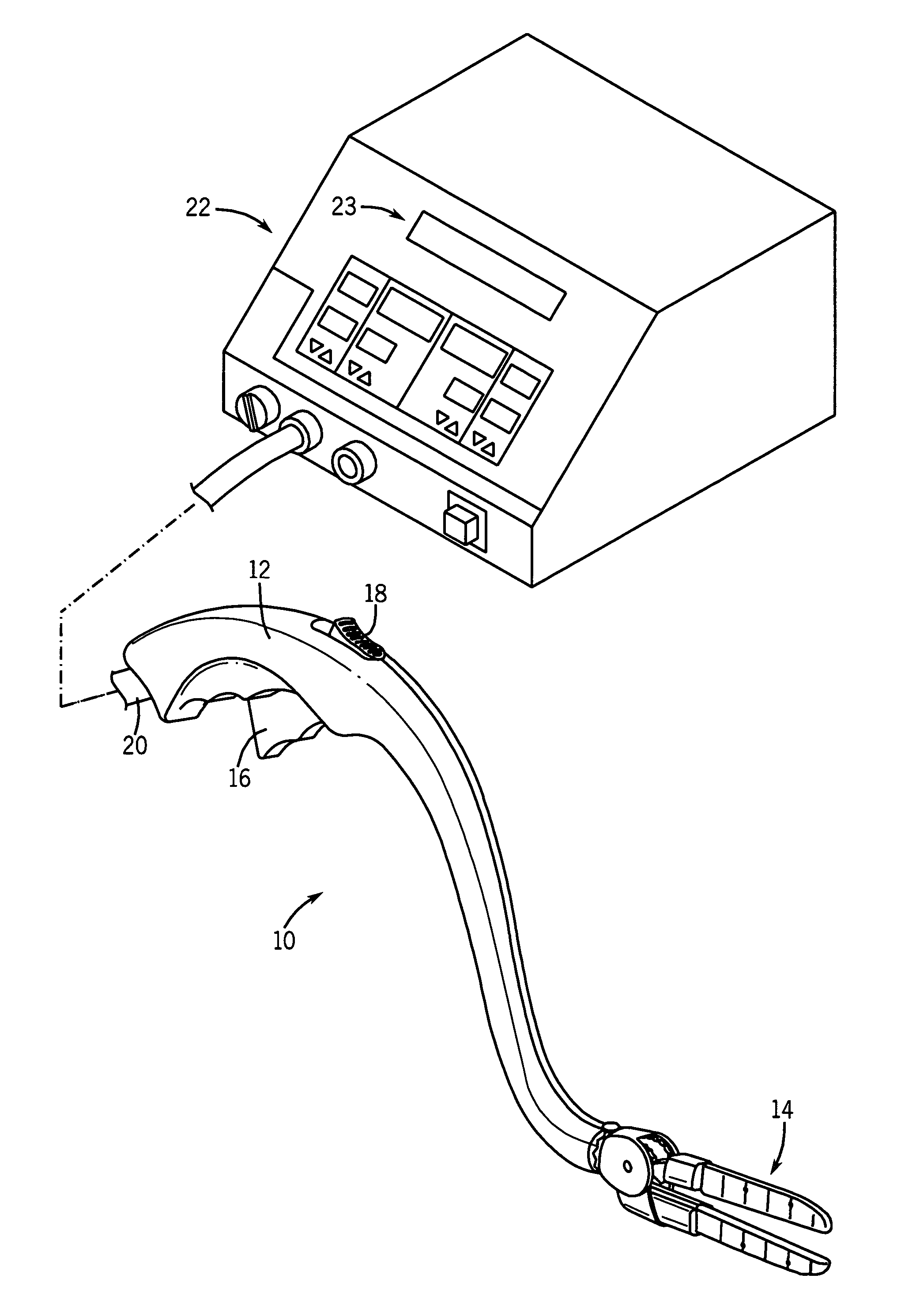
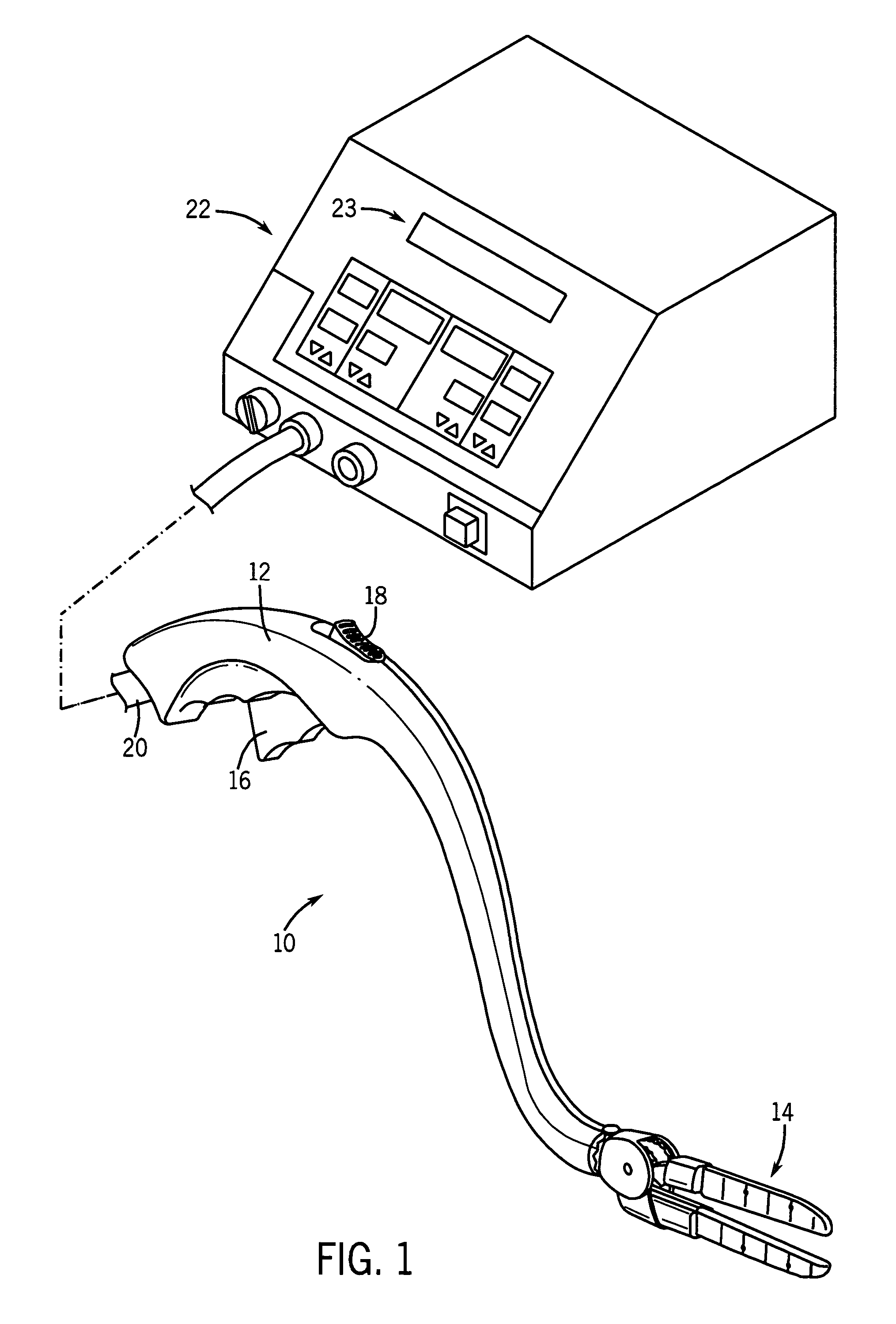
[0025]Referring to FIG. 1, a tissue ablation device, shown as a bipolar ablation device 10 has a handle 12 and an ablation head 14. A trigger 16 may be used by a surgeon to control certain functions of the ablation head 14. A switch, shown as locking mechanism 18, may be utilized to lock the ablation head 14 into position during a surgical procedure.

[0026]Further referring to FIG. 1, in an exemplary embodiment of a tissue ablation system, bipolar ablation device 10 may be partially controlled by and may provide feedback to a control device, such as generator 22. A cord 20 serves as a conduit for various smaller cords and tubes between generator 22 and ablation device 10. For example, cord 20 may house a power line for ablation head 14, saline irrigation lines to and from ablation head 14, and various other wires and cords sending signals to and receiving signals from ablation head 14. An exemplary bipolar ablation device having many of the features described with respect to FIG. 1 i...


PUM


Abstract

A tissue ablation device has a handle and an ablation head coupled to the handle. The ablation head has a first jaw, a second jaw, and an ablative element coupled to at least one of the first and second jaws. A thickness measurement device may be coupled to the ablation device to indicate the distance separating the first and second jaws. Further, a force measurement device may be coupled to the ablation device to measure the force being applied by the first and second jaws to a piece of tissue. Further, a strain measurement device may be coupled to the ablation device to indicate the strain resulting in a piece of tissue disposed between the first and second jaws when a stress is applied to the tissue.

Description

FIELD OF THE INVENTION[0001]The present invention relates to tissue ablation devices generally, and more particularly to devices adapted to ablate lines of tissue, for example for use in conjunction with an electrosurgical version of the Maze procedure. More particularly, the invention relates to an ablation device that aids in the measurement of tissue thickness and monitoring the transmurality of lesions.BACKGROUND OF THE INVENTION[0002]Various types of electrophysiology devices are used for ablating tissue. Typically, such devices include a conductive tip or blade which serves as one electrode in an electrical circuit which is completed via a grounding electrode coupled to the patient. With sufficiently high levels of electrical energy between the two electrodes, heat is generated which is sufficient to denature proteins within the tissue and cause cell death.[0003]It is well known that by controlling the energy level, the amount of heat generated and degree of tissue damage can ...

Claims


Application Information

Patent Timeline
Patent Type & Authority Patents(United States)
IPC IPC(8): A61B18/14A61B19/00
CPCA61B18/1442A61B2018/00666A61B2018/1861A61B2019/461A61B2019/464A61B2090/061A61B2090/064
Inventor FRANCISCHELLI, DAVID E.WARMAN, EDUARDO N.MEHRA, RAHUL
Owner MEDTRONIC INC
Learn More