Piezoelectric speaker and method of manufacturing the same

a piezoelectric speaker and piezoelectric technology, applied in the direction of piezoelectric/electrostrictive transducers, transducer types, electrical transducers, etc., can solve the problems of degrading sound quality, peak-dip of output sound pressure, and high sound pressure, so as to reduce distortion of sound and reduce the frequency band. , the effect of high sound pressur

Active Publication Date: 2012-12-18
ELECTRONICS & TELECOMM RES INST
View PDF13 Cites 4 Cited by
  • Summary
  • Abstract
  • Description
  • Claims
  • Application Information

AI Technical Summary

Benefits of technology

[0012]The present invention is directed to a small piezoelectric speaker and a method of manufacturing the same that are capable of obtaining high sound pressure in a low frequency band and reducing distortion of sound.
[0013]According to one aspect of the present invention, a piezoelectric speaker includes: a piezoelectric thin film for converting an electric signal into a physical vibration signal; an upper electrode and a lower electrode formed on and beneath the piezoelectric thin film; a damping material layer formed below the piezoelectric thin film with the upper and lower electrodes formed thereon and therebeneath; an acoustic diaphragm attached to the piezoelectric thin film to have an inclined structure in which the acoustic diaphragm is horizontally turned from the piezoelectric thin film with the damping material layer interposed therebetween; and a frame for fixing the acoustic diaphragm using an adhesive material with high elasticity.

Problems solved by technology

However, in the piezoelectric speaker having this structure, since the vibration of the piezoelectric vibrator must be delivered to the diaphragm via an elastic body for vibration delivery, the vibration of the piezoelectric vibrator must be very great and the diaphragm must be larger than the piezoelectric vibrator.
Further, when the vibration is delivered, unnecessary resonance may occur, causing peak-dip of output sound pressure, and sound may be distorted, degrading sound quality.
However, it is difficult to reproduce sound in a low frequency band because the metallic diaphragm is thicker than the piezoelectric material.
It is also difficult to embody a rich sound stage due to cool and sharp tones caused by a metal material of the metallic diaphragm.
Further, since unnecessary resonance may be caused by a frame for supporting the metallic diaphragm, sound may be easily distorted.
It is difficult to make the conventional piezoelectric speakers in a small size because the piezoelectric speakers have large diaphragms and also to reproduce sound in a low frequency band due to their relatively thick diaphragms.
Further, in the conventional piezoelectric speakers, a standing wave is created by a structural symmetry between the piezoelectric thin film and the diaphragm, such that sound can be readily distorted.

Method used


Image

  • Piezoelectric speaker and method of manufacturing the same
  • Piezoelectric speaker and method of manufacturing the same
  • Piezoelectric speaker and method of manufacturing the same

Examples


first exemplary embodiment

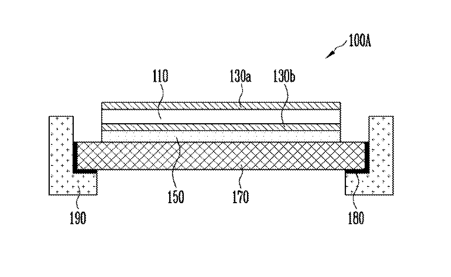
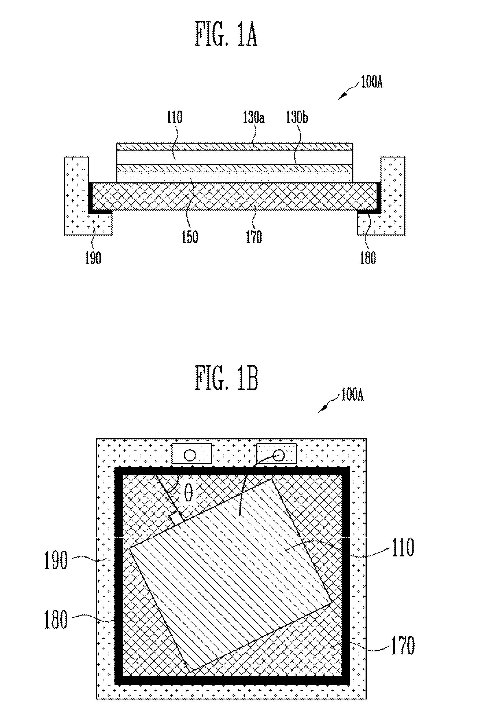
[0031]FIGS. 1A and 1B illustrate a piezoelectric speaker 100A according to a first exemplary embodiment of the present invention.

[0032]Referring to FIGS. 1A and 1B, the piezoelectric speaker 100A according to the first exemplary embodiment of the present invention includes a piezoelectric thin film 110 for converting an electric signal into a physical vibration signal, an upper electrode 130a and a lower electrode 130b formed on and beneath the piezoelectric thin film 110, respectively, a damping material layer 150 formed below the piezoelectric thin film 110 with the upper and lower electrodes formed thereon and therebeneath, an acoustic diaphragm 170 attached to the piezoelectric thin film 110 in an inclined structure with the damping material layer 150 interposed therebetween, and a frame 190 for fixing the acoustic diaphragm 170 using an adhesive material 180 with high elasticity.

[0033]The piezoelectric thin film 110 may be formed of a polycrystalline ceramic material such as le...

second exemplary embodiment

[0069]FIG. 4 illustrates a piezoelectric speaker 100B according to a second exemplary embodiment of the present invention.

[0070]Referring to FIG. 4, the piezoelectric speaker 100B according to the second exemplary embodiment of the present invention has the same structure as the piezoelectric speaker 100A shown in FIG. 1A except that a rear acoustic hole 190a of about 1 to 2 mm is formed at a center of the frame 190.

[0071]To form the rear acoustic hole 190a, the frame 190 may have a predetermined interval from the acoustic diaphragm 170 and have a thickness of 1.5 to 2 mm while surrounding a membrane of the speaker.

[0072]The rear acoustic hole 190a is provided to adjust damping when the acoustic diaphragm 170 vibrates. A peak-dip phenomenon often occurring in the piezoelectric speaker can be mitigated by adjusting the damping of the acoustic diaphragm 170 through the rear acoustic hole 190a and a soft tone can be provided by correcting flat output sound pressure in an entire frequen...

third exemplary embodiment

[0073]FIGS. 5A and 5B illustrate a piezoelectric speaker 100C according to a third exemplary embodiment of the present invention.

[0074]Referring to FIGS. 5A and 5B, the piezoelectric speaker 100C according to the third exemplary embodiment of the present invention has the same structure as the piezoelectric speaker 100A shown in FIG. 1A except that a high elastic acoustic diaphragm 170 is etched and shaped in a predetermined pattern to form a groove 170a.

[0075]The groove 170a of the acoustic diaphragm 170 serves as a spring so that the acoustic diaphragm 170 can vibrate more flexibly, thereby further reinforcing the output sound pressure of the speaker.

[0076]As described above, in the piezoelectric speaker according to the present invention, the acoustic diaphragm 170 is thicker than the piezoelectric thin film 110 and is formed of a more flexible and higher elasticity material than the piezoelectric thin film 110, and the piezoelectric thin film 110 is attached to the acoustic dia...


PUM

PropertyMeasurementUnit
inclination angleaaaaaaaaaa
thicknessaaaaaaaaaa
thicknessaaaaaaaaaa

Abstract

In a piezoelectric speaker, an acoustic diaphragm is thicker than a piezoelectric thin film and is formed of a more flexible and higher elasticity material than the piezoelectric thin film, thereby greatly improving output sound pressure in a low frequency band and reducing sound distortion. Further, the piezoelectric thin film is attached to the acoustic diaphragm in an inclined structure in which the piezoelectric thin film is horizontally turned from the acoustic diaphragm, thereby preventing a standing wave from being created by structural symmetry and minimizing sound distortion.

Description

CROSS-REFERENCE TO RELATED APPLICATION[0001]This application claims the benefit of Korean Patent Application No. 10-2009-0120935, filed Dec. 8, 2009, the disclosure of which is hereby incorporated herein by reference in its entirety.BACKGROUND[0002]1. Field of the Invention[0003]The present invention relates to a piezoelectric speaker and a method of manufacturing the same, and more particularly, to a small piezoelectric speaker and a method of manufacturing the same that are capable of obtaining high sound pressure in a low frequency band and reducing distortion of sound.[0004]2. Discussion of Related Art[0005]A piezoelectric speaker has a smaller thickness, a greater weight and a lower power consumption than an existing voice coil motor (VCM)-type speaker. Accordingly, the piezoelectric speaker is widely used for small, thin and lightweight portable terminals.[0006]Examples of a conventional piezoelectric speaker include a piezoelectric speaker with a piezoelectric vibrator, a pie...

Claims


Application Information

Patent Timeline
Patent Type & Authority Patents(United States)
IPC IPC(8): H04R25/00
CPCH04R31/006H04R17/00H04R31/00H04R17/02H04R1/02H04R17/10Y10T29/49005Y10T29/49115Y10T29/42H03H9/174H10N30/06H10N30/01
Inventor KIM, HYE JINLEE, SUNG QLEE, HONG YEOLPARK, KANG HOKIM, JONG DAEKOO, KUN MO
Owner ELECTRONICS & TELECOMM RES INST
Why Eureka
Try Eureka