
Custom radiographically designed cutting guides and instruments for use in total ankle replacement surgery

a cutting guide and radiographical design technology, applied in the field of total ankle replacement surgery, can solve the problems of occupying valuable operating room time, difficult to work, and complex structure, and achieve the effects of reducing operative time, improving surgical precision, and simplifying operative procedures

Active Publication Date: 2012-12-25
LIAN GEORGE JOHN
View PDF23 Cites 254 Cited by
  • Summary
  • Abstract
  • Description
  • Claims
  • Application Information

AI Technical Summary

Benefits of technology

"The invention provides a system for improving the precision of bone cuts and simplifying joint replacement surgery. It includes custom guides designed using preoperative CAT scan or MRI scan analysis and a set of instrumentalities for use with the guides. This system improves the precision of bone cuts, reduces the need for a large external frame to hold the ankle immobile, simplifies the operative procedure, decreases the operative time, minimizes the need for intra-operative fluoroscopy, and allows better correction of deformities by independent bone cuts and reaming of the tibia and talus bones. The system also includes a computer-based method for making the custom guides. Overall, the invention enhances the precision and effectiveness of joint replacement surgery."

Problems solved by technology

Although the existing technique used to define the bone cuts for this prosthesis can be accurate, it is very complex, thereby rendering it problematic to work with.
Although the above-delineated technique is accurate, its complexity has disadvantages.
For example, the frame that holds the leg must be constructed sterilely for each patient, a process that takes up valuable operating room time.
Additionally, the process of determining the proper alignment of the ankle in the frame prior to cutting the bone is technically exacting, and also time-consuming.
There is often a significant amount of fluoroscopic imaging required during the alignment process.
Another problem with this system, and with all of the existing systems for total ankle replacement, is difficulty in correcting angular deformities that are present.

Method used


Image

  • Custom radiographically designed cutting guides and instruments for use in total ankle replacement surgery
  • Custom radiographically designed cutting guides and instruments for use in total ankle replacement surgery
  • Custom radiographically designed cutting guides and instruments for use in total ankle replacement surgery

Examples


Embodiment Construction

[0066]Considering the drawings, wherein like reference numerals denote like parts throughout the various drawing figures, reference numeral 10 is directed to a system for use in total ankle replacement surgery.

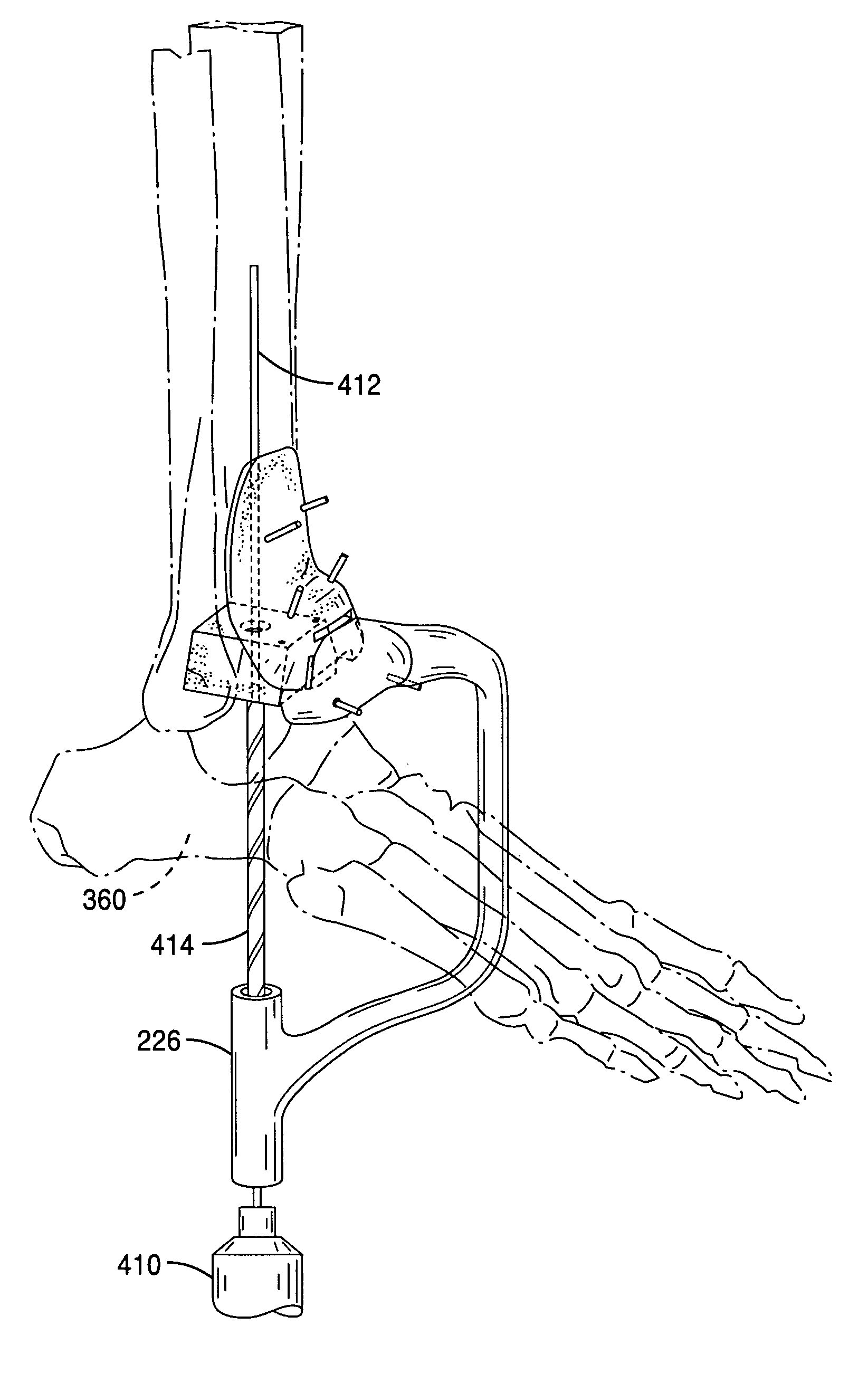
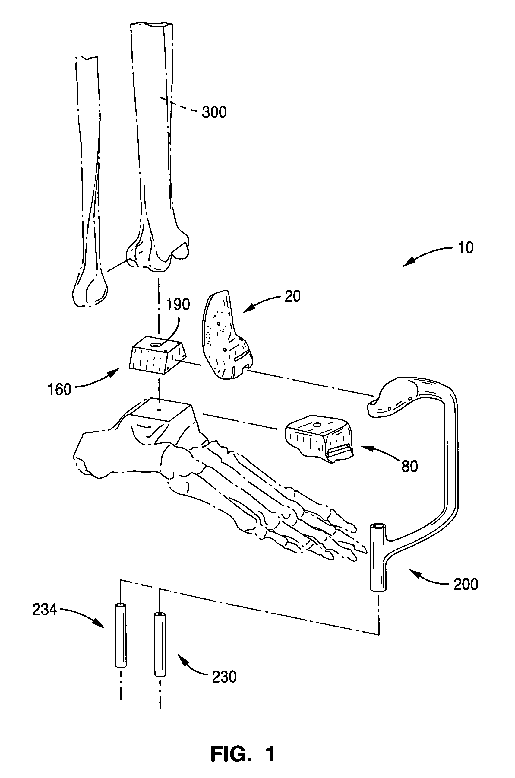
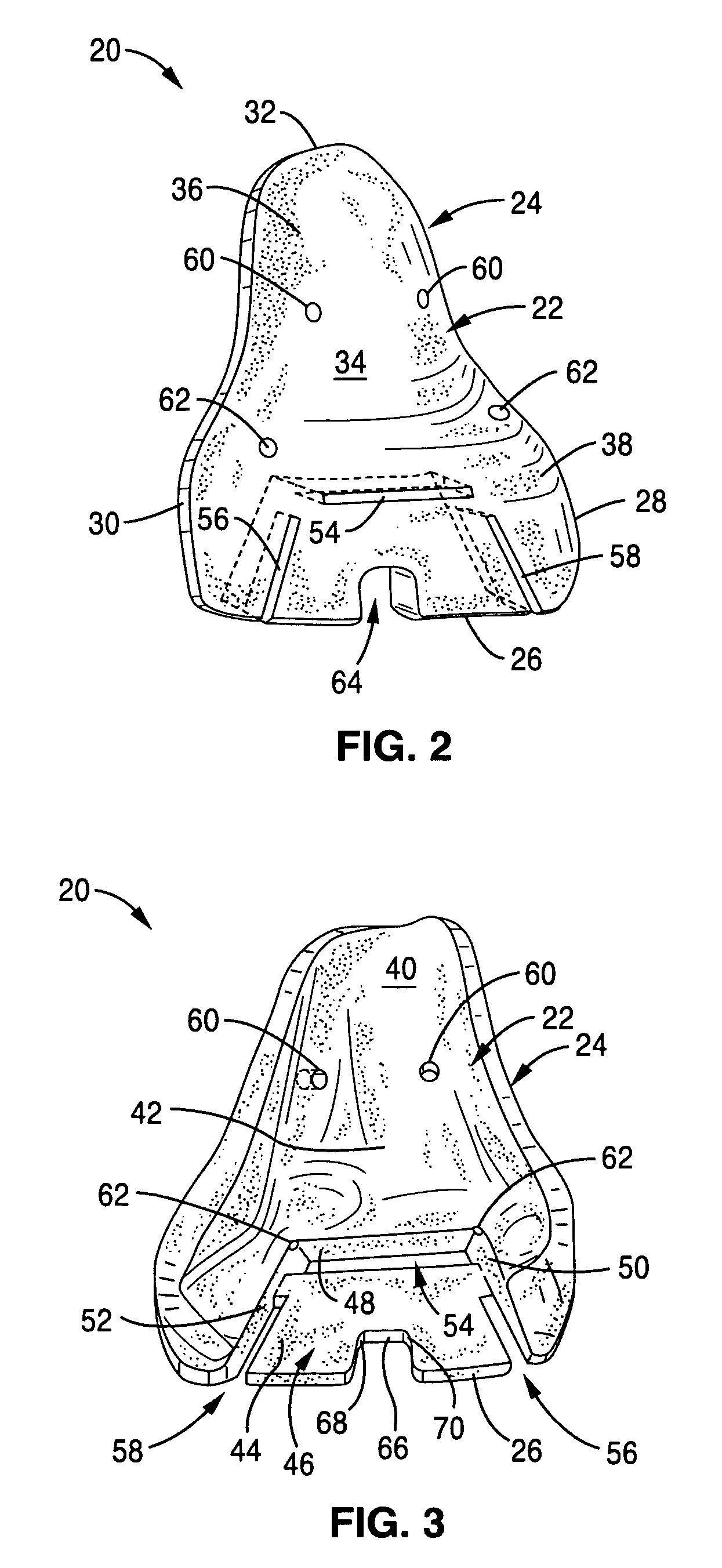
[0067]Referring to FIG. 1, and in one embodiment, the system 10 is comprised of a set of two patient-specific, radiographically designed, custom-made cutting guides: a custom tibial cutting guide 20 and a custom talar cutting guide 80. Additionally, the system 10 is comprised of a tibial reaming guide 160 circumscribing and aligning a removable, cannulated reaming bit 190. The system 10 is further comprised of a C-shaped outrigger alignment guide 200 that receives two removable, alternate inner sleeve guides: a cylindrically shaped inner sleeve wire guide 230 and a cylindrically shaped inner sleeve drill and driver bit guide 234. Moreover, and referring to FIGS. 15 and 17, the system 10 is comprised of a skeleton cage or first frame member 240 and a double fork cage or second ...


PUM


Abstract

A system comprised of custom radiographically designed tibial and talar cutting guides, a tibial reaming guide and bit, and instrumentalities for use in total ankle replacement surgery and a computer-based system and method for making the custom radiographically designed tibial and talar cutting guides.

Description

CROSS-REFERENCE TO RELATED APPLICATIONS[0001]This application claims priority under 35 U.S.C. section 119(e) to U.S. provisional patent application No. 61 / 212,533, filed Apr. 13, 2009 and to U.S. provisional application No. 61 / 270,203, filed Jul. 6, 2009, both disclosures of which are incorporated herein by reference in their entireties.FIELD OF THE INVENTION[0002]This invention relates generally to a system for use in total ankle replacement surgery, and, in particular, to a system comprised of custom radiographically designed cutting guides and instruments for use in total ankle replacement surgery.BACKGROUND OF THE INVENTION[0003]Total joint replacement is an orthopedic technique in which the diseased ends of bone at a joint are removed and replaced by a combination of metal and plastic prostheses. Joint replacement surgery is done to relieve pain and retain motion of the joint. Total joint replacement is very successful in the larger joints of the lower extremity, the hip and kn...

Claims


Application Information

Patent Timeline
Patent Type & Authority Patents(United States)
IPC IPC(8): A61F5/00
CPCA61B17/15A61B17/1739A61F2/4202A61B17/1615A61B17/1682A61B2019/508A61F2/4606A61F2002/30616A61F2002/4205A61F2002/4207A61B2017/1775A61B2017/568A61B2034/108A61B17/1775
Inventor LIAN, GEORGE JOHN
Owner LIAN GEORGE JOHN
Learn More