Method for enhancing contrast in infrared images

Active Publication Date: 2012-12-25
FLIR SYST AB
View PDF7 Cites 17 Cited by
  • Summary
  • Abstract
  • Description
  • Claims
  • Application Information

AI Technical Summary

Benefits of technology

[0012]e. replacement of the luminance component in the radiometric colour image with the scaled, filtered contrast-increased original image's luminance component.
[0013]The method for which a patent is sought comprises an IR-applied method through which radiated or reflected energy/heat is visualised with a colour scale and where each colour, given known or assumed physical values for transmission, reflection and atmospheric damping in the measured wavelength range, corresponds to an absolute temperatur

Problems solved by technology

An absolute temperature cannot, however,

Method used


Image

  • Method for enhancing contrast in infrared images
  • Method for enhancing contrast in infrared images

Examples


Embodiment Construction

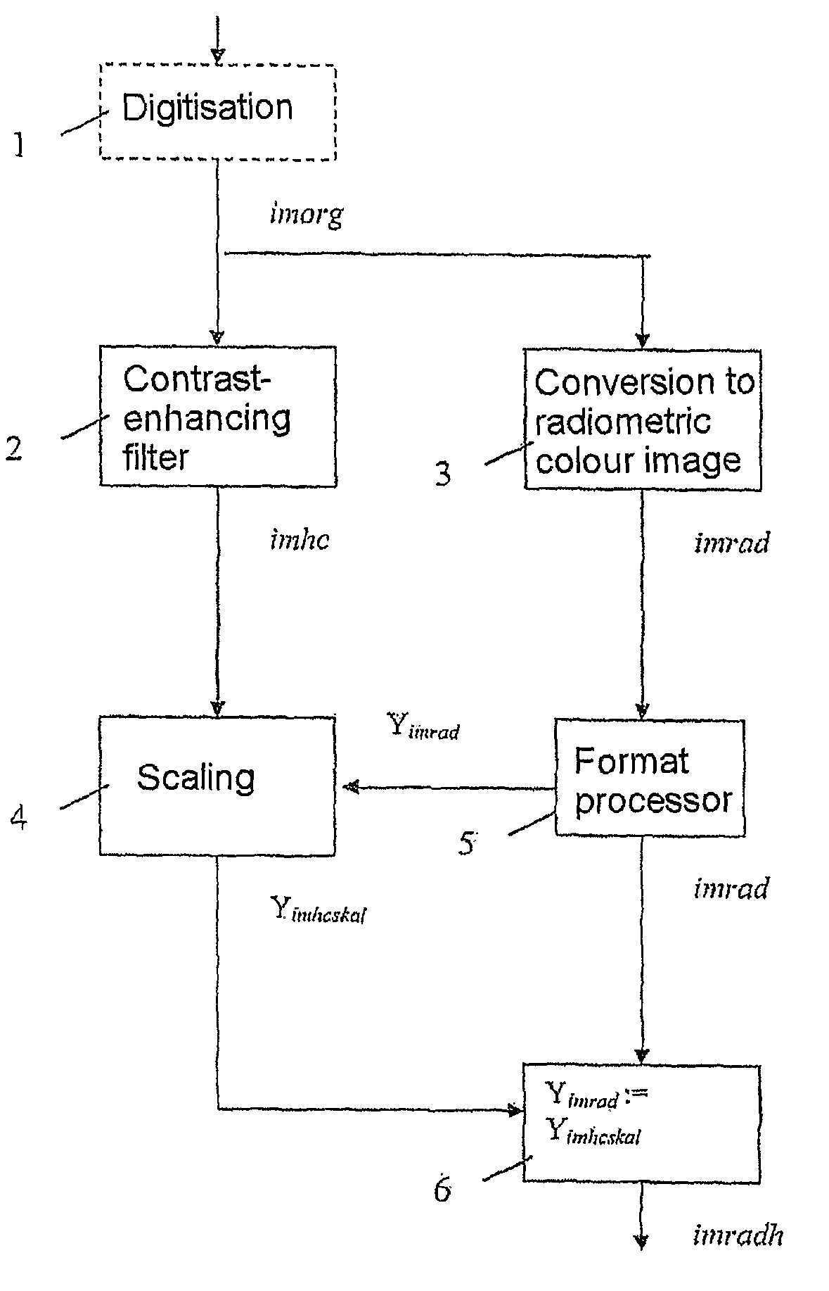
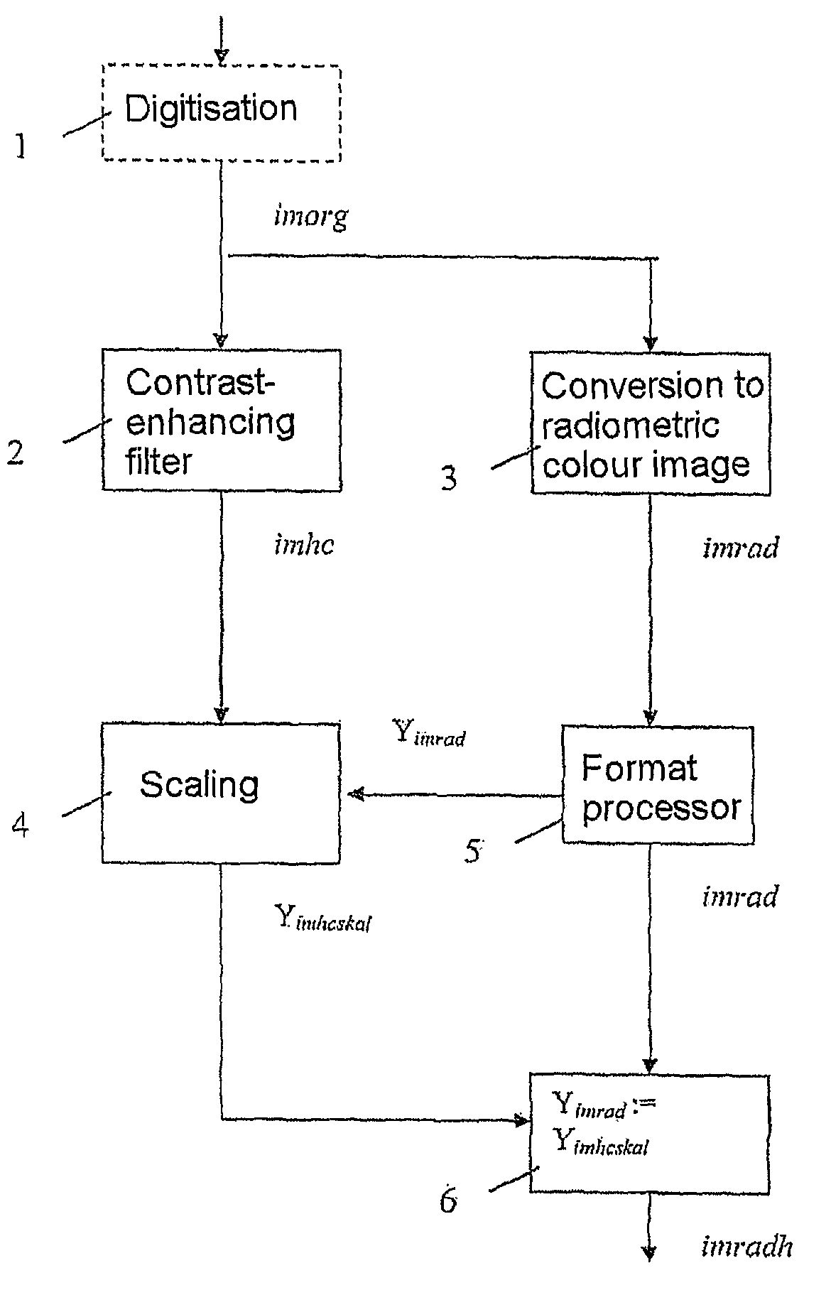
[0018]For image processing, we use as a starting point an original image which, if not already in digital format, is digitalised in block 1, illustrated by dashed lines. The original image in digital format is called imorg. The digital original image is filtered to increase the image's contrast. This takes place in a block 2. The filtration can be performed according to the article referred to above or other appropriate contrast-increasing method. The filtered image is called imhc (high contrast) and has a high contrast but lacks a direct connection between the signal level and the energy measured from the scene.

[0019]In parallel with the filtration of the original image, the digital original image is converted into a synthetic, radiometric, pseudocolour image. This happens in a block 3 and the radiometric colour image is called imrad. The conversion takes place based on a chosen colour range so that, given known or assumed physical criteria for the relevant wavelength band, each co...


PUM


Abstract

A method for image processing comprising filtration and conversion to a radiometric color image based on an original image. The method gives the processed image high spatial resolution combined with high dynamic resolution. The original image is made available in digital format. Contrast-increasing filtration is performed on the original digital image. The original digital image is converted into a radiometric pseudocolor image based on a chosen color range in which each color corresponds to an absolute measured, radiated or reflected quantity of energy within a certain wavelength band and where the images are represented in a format containing a luminance component. The filtered contrast-increased original image is scaled in terms of the luminance component in the radiometric color image. The luminance component in the radiometric color image is replaced with the scaled, filtered contrast-increased luminance component of the original image.

Description

CROSS-REFERENCE TO RELATED APPLICATIONS[0001]This application claims priority to Swedish patent application 0700240-5 filed 1 Feb. 2007 and is the national phase under 35 U.S.C. §371 of PCT / SE2008 / 000082filed 30 Jan. 2008.FIELD OF THE INVENTION[0002]The present invention relates to a method for image processing comprising the filtering and conversion to a radiometric colour image based on an original image.BACKGROUND OF THE INVENTION[0003]Systems which generate images, be they IR, MR, radar or x-ray, have two different requirements. The one requirement can be seen as spatial resolution and the other dynamic resolution. The requirement for spatial resolution comes from the need to resolve small objects and the dynamic resolution from the need to be able to resolve and measure signal levels on an image surface. For example, with radar, small objects such as aeroplanes may need to be detected and, with another, weather radar, the density of a cloud may need to be established to determi...

Claims


Application Information

Patent Timeline
IPC IPC(8): G06K9/00G06K9/40
CPCG06T5/50G06T11/001G06T2207/10048G06T2207/10032H04N5/57
Inventor HOGASTEN, NICOLASMCCARTHY, GRAHAM
Owner FLIR SYST AB
Why Eureka
Try Eureka