
Method and system for dynamically replicating data within a distributed storage system

a storage system and data technology, applied in the field of database replication, can solve the problems of affecting the reliability of data replication, the inability to replicate large quantities of data on a planetary scale, and the inability to use network paths and data centers for a long time, so as to improve the efficiency of network resources and accelerate the replication of data in distributed databases. , the effect of reducing the cost of data replication

Active Publication Date: 2012-12-25
GOOGLE LLC
View PDF50 Cites 74 Cited by
  • Summary
  • Abstract
  • Description
  • Claims
  • Application Information

AI Technical Summary

Benefits of technology

[0018]Thus methods and systems are provided that make replication of data in distributed databases faster, and enable more efficient use of network resources. Faster replication results in providing users with updated information (or access to information) more quickly; and more efficient usage of network bandwidth leaves more bandwidth available for other tasks, making other processes run faster.

Problems solved by technology

Replication of large quantities of data on a planetary scale can be both slow and inefficient.
In particular, the long-haul network paths have limited bandwidth.
In addition, network paths and data centers sometimes fail or become unavailable for periods of time (both unexpected outages as well as planned outages for upgrades, etc.).
Generally, replicated systems do not handle such outages gracefully, often requiring manual intervention.
When replication is based on a static network topology and certain links become unavailable or more limited, replication strategies based on the original static network may be inefficient or ineffective.
Therefore it is a challenge to design an optimized real-time data replication scheme within a large distributed storage system such that the scheme not only consumes as little resource as possible but also improves the services offered by the distributed storage system.

Method used


Image

  • Method and system for dynamically replicating data within a distributed storage system
  • Method and system for dynamically replicating data within a distributed storage system
  • Method and system for dynamically replicating data within a distributed storage system

Examples


Embodiment Construction

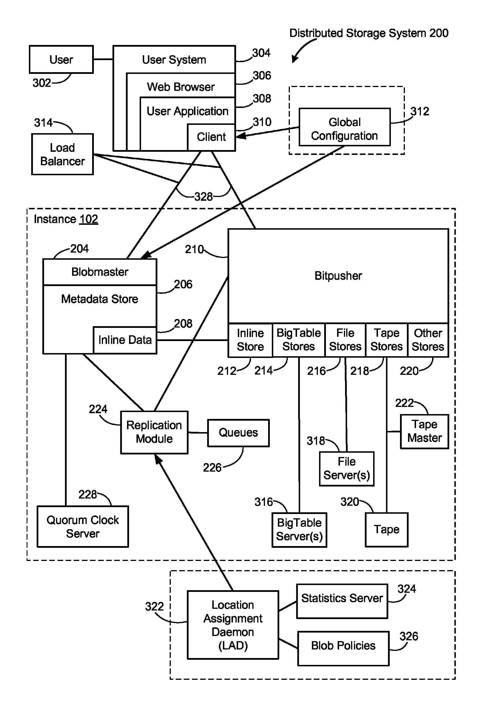
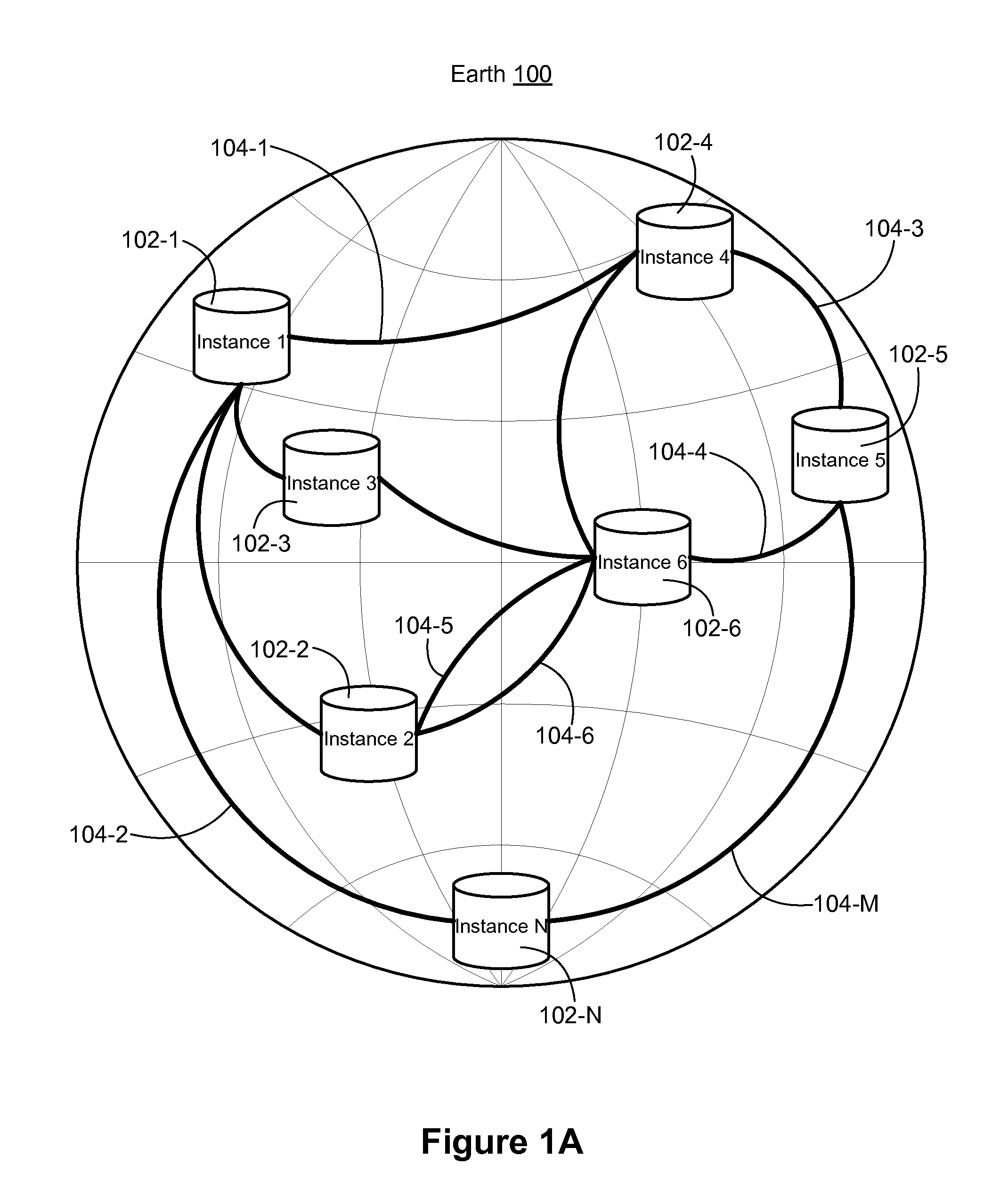
[0033]The present specification describes a distributed storage system. In some embodiments, as illustrated in FIG. 1A, the distributed storage system is implemented on a global or planet-scale. In these embodiments, there are a plurality of instances 102-1, 102-2, . . . 102-N at various locations on the Earth 100, connected by network communication links 104-1, 104-2, . . . 104-M. In some embodiments, an instance (such as instance 102-1) corresponds to a data center. In other embodiments, multiple instances are physically located at the same data center. Although the conceptual diagram of FIG. 1 shows a limited number of network communication links 104-1, etc., typical embodiments would have many more network communication links. In some embodiments, there are two or more network communication links between the same pair of instances, as illustrated by links 104-5 and 104-6 between instance 2 (102-2) and instance 6 (102-6). In some embodiments, the network communication links are c...


PUM


Abstract

A server computer at a first storage sub-system of a distributed storage system receives from a client a first client request for an object. If the object is not present in the first storage sub-system, the server computer identifies a second storage sub-system of the distributed storage system as having a replica of the requested object, the requested object including content and metadata. The server computer submits an object replication request for the requested object to the second storage sub-system and independently receives the content and metadata of the requested object from the second storage sub-system. The server computer generates a new replica of the object at the first storage sub-system using the received metadata and content and returns the metadata of the new replica of the object to the client.

Description

PRIORITY[0001]This application claims priority to U.S. Provisional Application Ser. No. 61 / 302,896, filed Feb. 9, 2010, entitled “Method and System for Dynamically Replicating Data Within a Distributed Storage System”, which is incorporated by reference herein in its entirety.TECHNICAL FIELD[0002]The disclosed embodiments relate generally to database replication, and more specifically to dynamic replication of data between two storage sub-systems of a distributed storage system.BACKGROUND[0003]For weakly mutable data, changes or mutations at one instance (or replica) of the data must ultimately replicate to all other instances of the database, but there is no strict time limit on when the updates must occur. This is an appropriate model for certain data that does not change often, particular when there are many instances of the database at locations distributed around the globe.[0004]Replication of large quantities of data on a planetary scale can be both slow and inefficient. In pa...

Claims


Application Information

Patent Timeline
Patent Type & Authority Patents(United States)
IPC IPC(8): G06F17/30
CPCG06F17/30581G06F16/275
Inventor DROBYCHEV, ALEXANDREKESSELMAN, ALEXANDERVICKREY, REBEKAH C.DACHILLE, FRANK C.DATUASHVILI, GEORGE
Owner GOOGLE LLC
Learn More