Hair clippers with electrically adjustable blades

Inactive Publication Date: 2013-01-01
HOLMES LONNIE
View PDF30 Cites 49 Cited by
  • Summary
  • Abstract
  • Description
  • Claims
  • Application Information

AI Technical Summary

Benefits of technology

[0006]The hair clippers of this invention use a self-contained motor-driven adjustment mechanism to adjust the relative position of the stationary and reciprocating blades of a common type of blade set. Two momentary switches operable by the thumb of the hand holding the clipper afford a barber total automatic adjustment with the clipper itself in an on or off condition. There is no need for two-handed fidgeting or selection of only a few discrete increments of length adjustment as with the commonly available models. Since the small gear motors used for the adjustment are brush type or brushless permanent magnet motors which are operated by direct current, the adjustment feature is most compatible with cordless clippers already using an on-board DC source in the form of a re-chargeable battery to drive the reciprocating blade. The invention will be described as a modification of a cordless clipper, although AC driven corded type clippers can also be modified with this feature by the addition of an on-board AC to DC power supply for the adjustment motor.
[0007]In the first embodiment, a modified blade set is used such that a gear rack is attached to the stationary blade. It is engaged with a worm gear pinion driven by a low speed gear motor through...

Problems solved by technology

The prior art does not reveal motor-powered continuous adjustability of the blade set which affords the...

Method used


Image

  • Hair clippers with electrically adjustable blades
  • Hair clippers with electrically adjustable blades
  • Hair clippers with electrically adjustable blades

Examples


first embodiment

[0020]FIG. 5 is a wiring diagram for FIGS. 3 and 4 wherein gearmotor 10 is a simple brush type permanent magnet type driven by a common “H-bridge” drive module 35. Battery 30 is used primarily to power clipper motor 24 through on / off switch 25. It is also used as the power source for the adjustment feature. Drive module 35 has two direction inputs for clockwise and counter-clockwise operation, an “ON” input, and power input and motor output connections as shown. In operation, if normally open switch 22 is pushed, a signal will flow through normally closed limit switch 17 energizing the ON input through isolation diode 36; motor 10 will be driven clockwise until either switch 22 is released or limit switch 17 is opened at the end of the excursion. Similarly, if switch 21 is pushed, counter-clockwise operation is achieved through limit switch 16 and isolation diode 37. Once a limit switch is opened, motor 10 can only be driven in the opposite direction until the open limit switch is a...

second embodiment

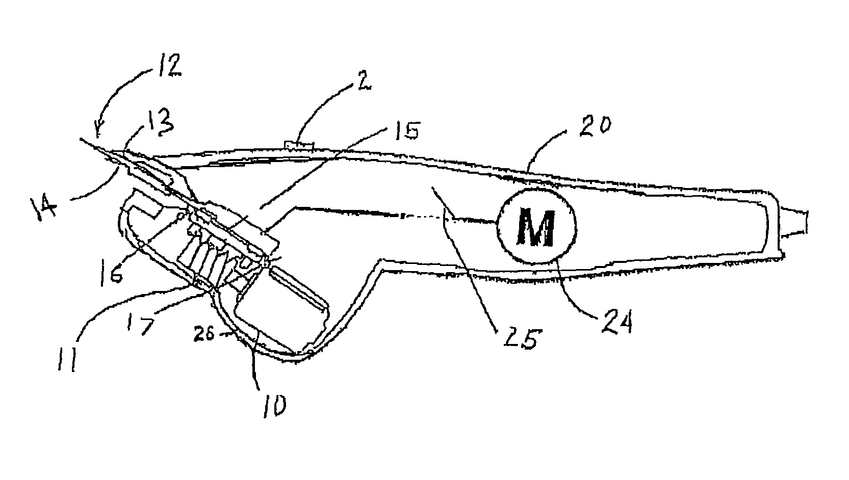
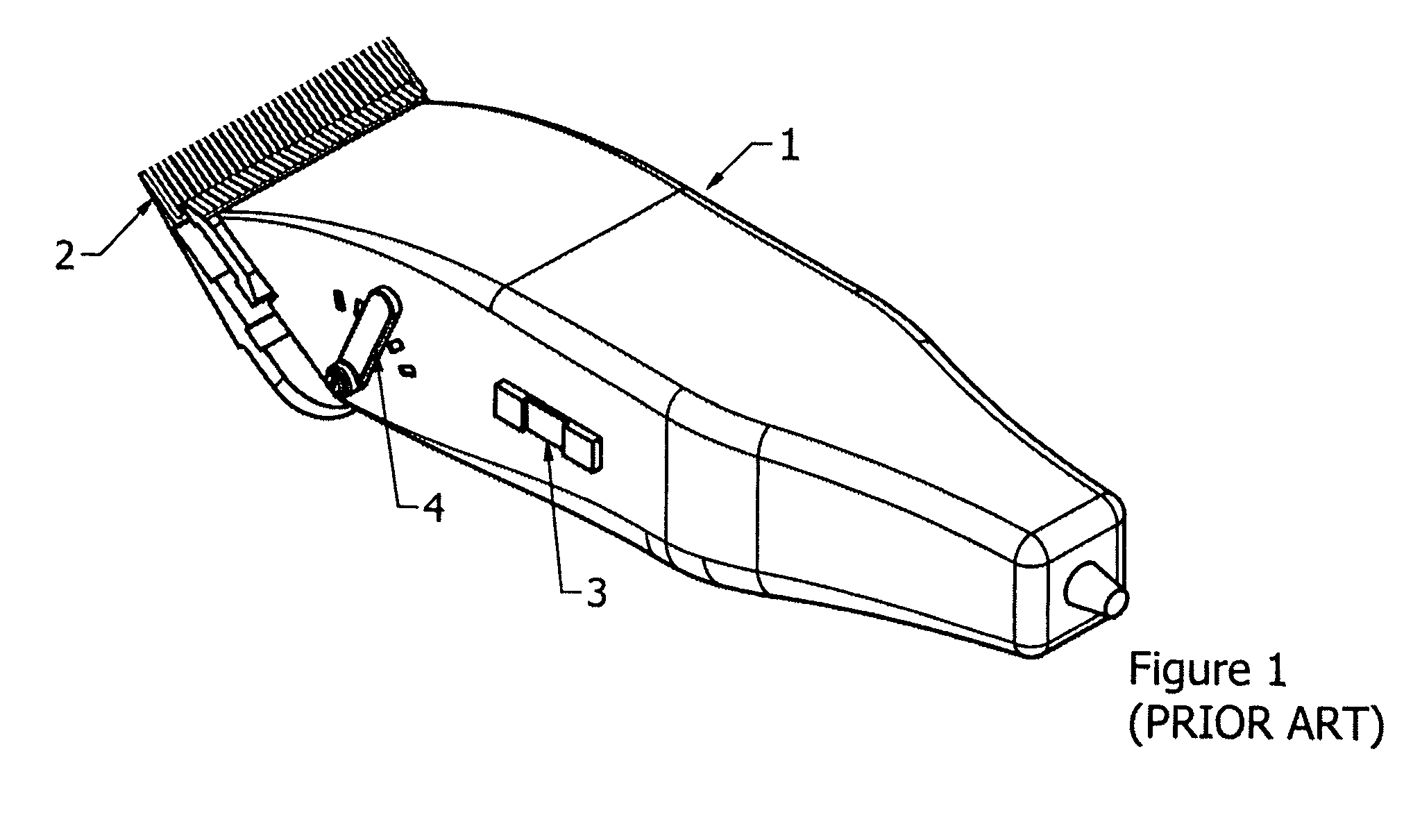
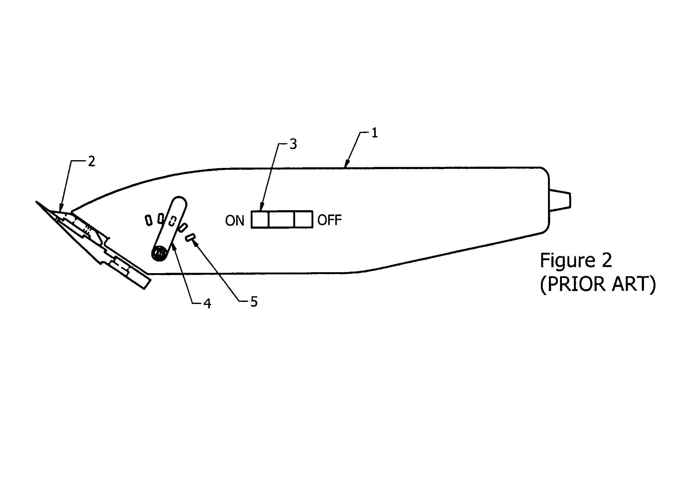
[0021]FIGS. 6 and 7 show top and side views of motor-driven minimum hair length adjustable hair clippers. The same circuit shown in FIG. 5 is completely applicable to this embodiment as well. The same momentary (“tap”) switches 21 and 22 are used to control motor 10 which is now placed at the back end of hair clipper 40. Except for the addition of switches 21 and 22, the housing 41 and internal mechanism is identical to that of the prior art cordless clipper shown in FIGS. 1 and 2. In this embodiment, a conventional blade set 12 and internal blade adjusting mechanism is used. The feature of this embodiment couples through the shaft formerly engaged with a manual handle 4. This is shown at the center of output gear 51. In the top view of FIG. 6, housing cover 42 is a plastic shell used to enclose the feature mechanism. In FIG. 7, this cover 42 is removed to reveal the mechanism; the position is shown in dashed lines. On the top edge of cover 42 is a tri-colored strip 43 with green re...


PUM

PropertyMeasurementUnit
Poweraaaaaaaaaa
Lengthaaaaaaaaaa

Abstract

The hair clippers use a self-contained motor-driven adjustment mechanism to adjust the relative position of the stationary and reciprocating blades of a common type of blade set. Two momentary switches operable by the thumb of the hand holding the clipper afford a barber total automatic adjustment with the clipper itself in an on or off condition. Since the small gear motors used for the adjustment are brush type or brushless permanent magnet motors which are operated by direct current, the adjustment feature is most compatible with cordless clippers already using an on-board DC source in the form of a re-chargeable battery to drive the reciprocating blade. The invention will be described as a modification of a cordless clipper, although AC driven corded type clippers can also be modified with this feature by the addition of an on-board AC to DC power supply for the adjustment motor.

Description

RELATED APPLICATIONS[0001]This application is based upon provisional application Ser. No. 61 / 117,434 filed Nov. 24, 2008, which application is incorporated by reference herein. Applicant claims priority under 35 USC §119(e) therefrom.FIELD OF THE INVENTION[0002]The present invention relates to hair cutting.BACKGROUND OF THE INVENTION[0003]Electrically operated hair clippers have been used for many years. Some of the commonly available models have a manual lever on the side to incrementally adjust the relative position between the stationary and the reciprocating blades in a blade set to adjust the minimum length of hair that is being clipped. Other prior art patents show infinite adjustability over a range. The prior art does not reveal motor-powered continuous adjustability of the blade set which affords the barber the ability to perform the adjustment even during the clipping activity by simply activating a switch.OBJECTS OF THE INVENTION[0004]It is therefore an object of the pres...

Claims


Application Information

Patent Timeline
IPC IPC(8): B26B19/02B26B19/28B26B19/38
CPCB26B19/205A61N1/3752Y10T29/49826Y10T29/49876B26B19/02B26B19/046B26B19/06B26B19/063B26B19/20A61B2090/031A61B17/8875B25B23/1427B25B23/0042
Inventor HOLMES, LONNIE
Owner HOLMES LONNIE
Why Eureka
Try Eureka