Dual clutch transmission

a clutch transmission and clutch technology, applied in mechanical equipment, transportation and packaging, gearing, etc., can solve the problems of limiting the installation possibilities of known transmissions, not considering the structural space required for their installation, etc., and achieve the effect of low production cost of transmissions

Active Publication Date: 2013-01-01
ZF FRIEDRICHSHAFEN AG
View PDF23 Cites 14 Cited by
  • Summary
  • Abstract
  • Description
  • Claims
  • Application Information

AI Technical Summary

Benefits of technology

[0006]The purpose of the present invention is to propose a dual clutch transmission of the type described at the start, with which on the one hand the shift-under-load transmission ratio steps can be produced with the least possible need for structural space, and on the other hand such that the transmission contains as few components as possible in order to keep the production costs of the transmission low.
[0007]Thus, a dual clutch transmission with only five wheel planes in the part-transmissions is produced, such that to enable winding gears the two part-transmissions can be coupled by means of the at least one additional shifting element. In this way, in the proposed dual clutch transmission a maximum number of transmission ratios can be produced with the fewest possible wheel planes, preferably such that all the forward gears and reverse gears can be shifted under load in sequence.
[0009]Thanks to the small number of wheel planes required, the axial length of the proposed transmission is short, whereby even front transverse mounting in vehicles is made possible. Since the dual clutch transmission according to the invention also contains winding gears and by virtue of its three-shaft configuration, multiple uses of individual wheel pairs or wheels are enabled, which leads to a saving of components in the transmission.
[0010]In the dual clutch transmission according to the invention so-termed dual wheel planes and / or single wheel planes can be provided. In a dual wheel plane, a respective idler gearwheel of each of the countershafts is associated with a fixed gearwheel of one of the transmission input shafts. In contrast, in a single wheel plane only one idler gearwheel of one countershaft is associated with a fixed gearwheel of one of the transmission input shafts. Since in each dual wheel plane at least one idler gearwheel can be used for at least two gears, owing to this possible multiple use of idler gearwheels, a given number of transmission ratios can be produced with fewer wheel planes. Thus, the structural length of the transmission is reduced.
[0021]It is conceivable to vary the possible arrangements indicated and also the number of toothed gearwheels and the number of coupling devices to realize still more load-shifting or non load-shifting gears in a manner that saves both structural space and components in the proposed dual clutch transmission. In addition, the respective arrangement positions of the coupling devices on the wheel planes can be varied. Furthermore, the action direction of the coupling devices can be changed or extended. A dual action coupling device can also be replaced by two single action coupling devices, and vice-versa.

Problems solved by technology

To produce the desired transmission ratio steps with the known dual clutch transmissions a substantial number of wheel planes are required, so that the structural space required for installing them is not inconsiderable.
This increases the structural space it occupies the axial direction, which considerably restricts the installation possibilities of the known transmission.

Method used


Image

  • Dual clutch transmission
  • Dual clutch transmission
  • Dual clutch transmission

Examples


first embodiment

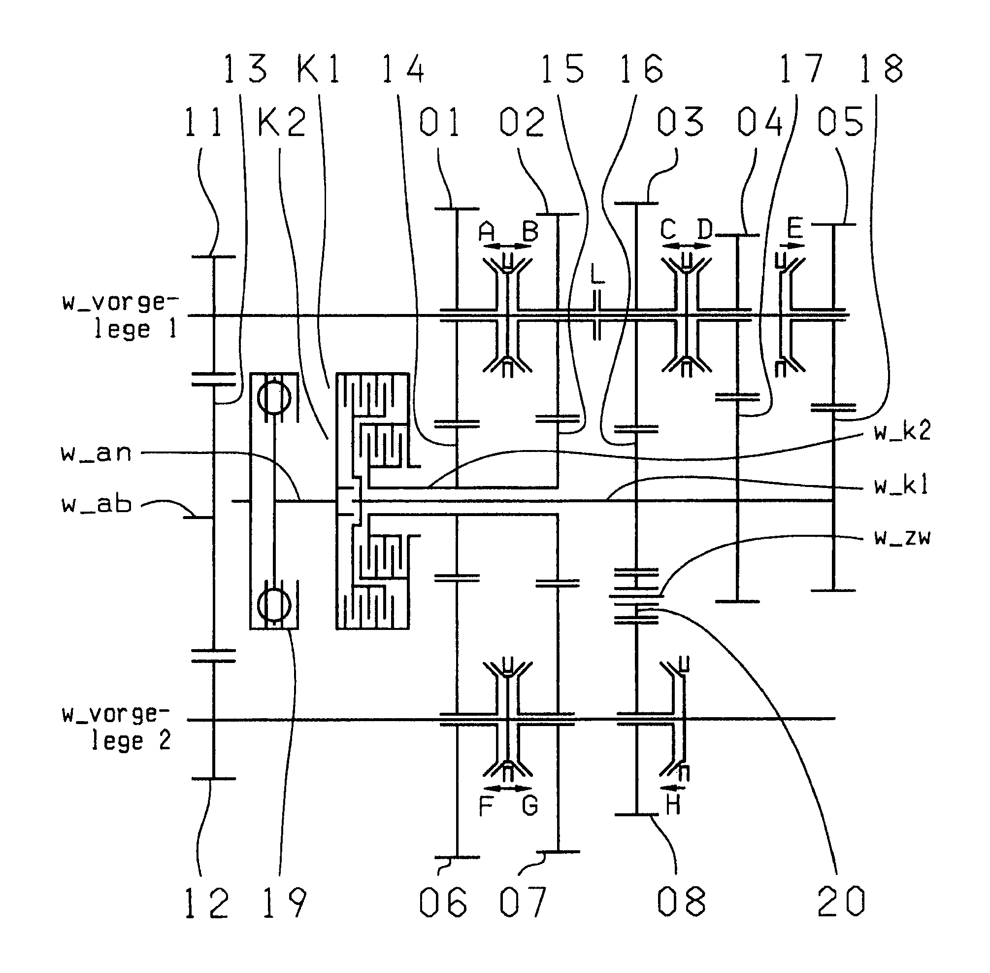
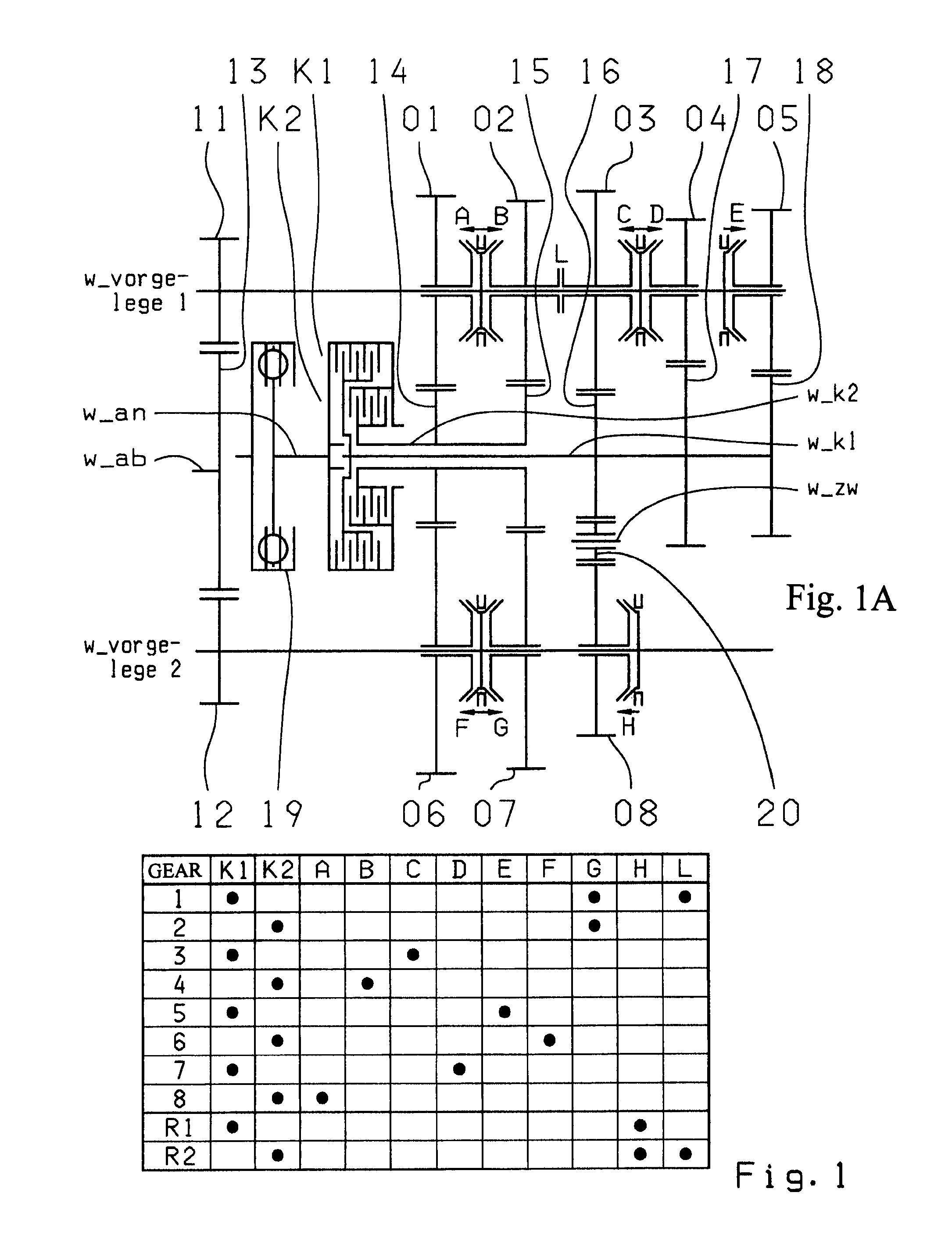
[0029]In the eight-gear dual clutch transmission according to the invention only five wheel planes are provided. In the first embodiment variant according to FIG. 1A the five wheel planes 01-06, 02-07, 03-08, 04-1705-18 are formed by two fixed gearwheels 14, 15 on the second transmission input shaft w_K2 and by three fixed gearwheels 16, 17, 18 on the first transmission input shaft w_K1, which mesh with five idler gearwheels 01, 02, 03, 04, 05 on the first countershaft w_vorgelege1 and with three idler gearwheels 06, 07, 08 on the second countershaft w_vorgelege2.

[0030]According to the first embodiment variant shown in FIG. 1A, the first, second and third wheel planes, 01-06, 02-07 and 03-08 respectively, are made as dual wheel planes. In contrast, the fourth and fifth wheel planes 04-17 and 05-18 respectively are each single wheel planes.

[0031]In the first wheel plane 01-06 the fixed gearwheel 14 of the second transmission input shaft w_K2 meshes both with the idler gearwheel 01 of...

second embodiment

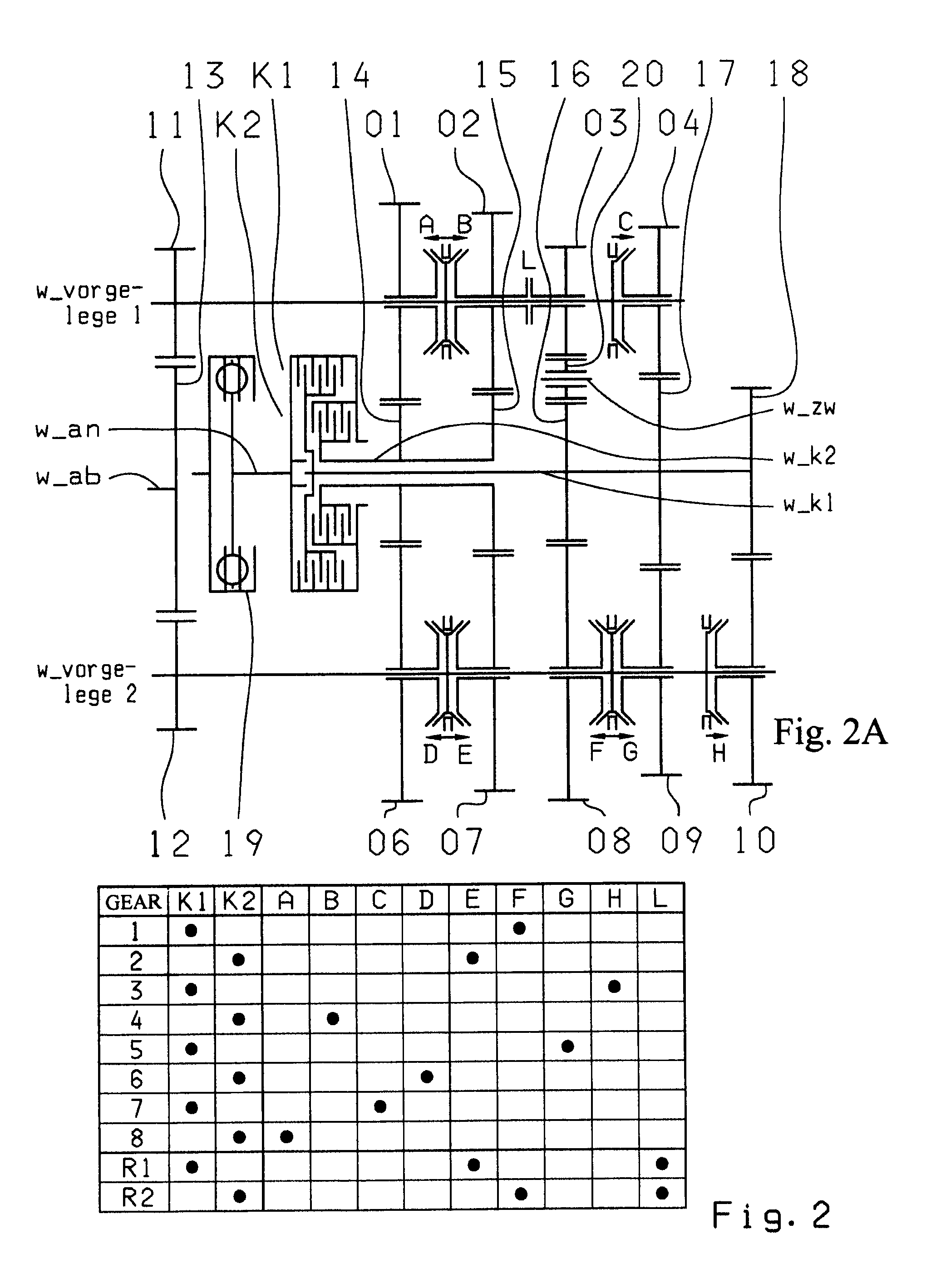
[0041]In the second embodiment variant shown in FIG. 2A, the five wheel planes 01-06, 02-07, 03-08, 04-0918-10 are formed by two fixed gearwheels 14, 15 of the second transmission input shaft w_K2 and three fixed gearwheels 16, 17, 18 of the first transmission input shaft w_K1, which mesh with four idler gearwheels 01, 02, 03, 04 of the first countershaft w_vorgelege1 and with five idler gearwheels 06, 07, 08, 09, 10 of the second countershaft w_vorgelege2.

[0042]According to the embodiment variant shown in FIG. 2A, the first, second, third and fourth wheel planes, 01-06, 02-07, 03-08 and 04-09 respectively, are all formed as dual wheel planes. In contrast, the fifth wheel plane 18-10 is a single wheel plane.

[0043]In the first wheel plane 01-06 the fixed gearwheel 14 of the second transmission input shaft w_K2 meshes both with the idler gearwheel 01 of the first countershaft w_vorgelege1 and with the idler gearwheel 06 of the second countershaft w_vorgelege2. The second wheel plane 0...


PUM


Abstract

A dual-clutch transmission comprising clutches with input sides coupled to an input shaft and output sides respectively coupled to first and second transmission input shafts, countershafts on which toothed idler gearwheels are mounted to rotate, toothed fixed gearwheels are coupled to the first and the second transmission input shafts and engage the idler gearwheels, coupling devices connect the idler gearwheel to one of the countershafts, drive output gearwheels are fixed to countershafts and drive an output shaft, and a shifting element couples the input shafts, such that eight forward gears and at least one reverse gear can be engaged. Five wheel planes are arranged in the transmission such that at least one winding gear can be engaged by the shifting element.

Description

[0001]This application is a National Stage completion of PCT / EP2008 / 063424 filed Oct. 8, 2008, which claims priority from German patent application serial no. 10 2007 049 270.9 filed Oct. 15, 2007.FIELD OF THE INVENTION[0002]The present invention concerns a dual clutch transmission for a vehicle.BACKGROUND OF THE INVENTION[0003]From the document DE 103 05 241 A1 a six-gear or seven-gear dual clutch transmission is known. The dual clutch transmission has two clutches, each connected on its input side to the drive input shaft and on its output side to one of the two respective transmission input shafts. The two transmission input shafts are arranged coaxially with one another. Further, two countershafts are arranged axis-parallel to the two transmission input shafts, whose idler gearwheels mesh with fixed gearwheels of the transmission input shafts. Moreover, coupling devices are held in a rotationally fixed manner but able to move axially on the countershafts, in order to be able to ...

Claims


Application Information

Patent Timeline
Patent Type & Authority Patents(United States)
IPC IPC(8): F16H3/08
CPCF16H3/006F16H3/093F16H2003/0807F16H2003/0826Y10T74/19228F16H2200/006F16H2200/0086Y10T74/19233F16H2003/0931
Inventor RIEGER, WOLFGANG
Owner ZF FRIEDRICHSHAFEN AG
Why Eureka
Try Eureka