Wind and water power generator ship

a generator ship and wind power technology, applied in the direction of electric generator control, machines/engines, mechanical equipment, etc., can solve the problems of low generation efficiency, loss of power, damage of resistance plates, etc., and achieve the effect of reducing construction costs and short construction tim

Active Publication Date: 2013-01-01
INJE UNIV IND ACADEMIC COOP FOUND
View PDF2 Cites 8 Cited by
  • Summary
  • Abstract
  • Description
  • Claims
  • Application Information

AI Technical Summary

Benefits of technology

[0011]Accordingly, the present invention has been made keeping in mind the above problems occurring in the related art, and is intended to provide a wind and water power generator ship, which is set afloat on running water so that the powers of both water and wind can be used, thereby increasing the efficiency of power generation.
[0012]Another purpose of the present invention is to provide a wind and water power generator ship which minimizes the loss in power because the plates warp less and have less slimming even at the resistance of running water or in the strong wind.
[0013]Furthermore, the present invention is also intended to provide a wind and water power generator ship that can operate under its own self-generated power by supplying electric power from running water and changing its direction depending on the direction of the wind.

Problems solved by technology

Although the inventions of the related art generate electricity using the resistance between an object, which is set afloat on running water, and the current of the water, the efficiency of generation is low because of the slow velocity of the water.
When the resistance plate or board meets resistance from the current of water from the front, it is rotated by 90° or more due to dislodgment, tilting, or slimming, which is caused by the velocity of the water, and thus loses power.
If the resistance plate is not tightly fixed, there is a danger of the resistance plate being damaged by the fast velocity of the water.
However, the wind power generation apparatuses of the related art have problems in that the efficiency of power generation is low because of a small turning moment and additional power for operation being required in a weak wind since the blades consume a large amount of force.

Method used


Image

  • Wind and water power generator ship
  • Wind and water power generator ship
  • Wind and water power generator ship

Examples


Embodiment Construction

[0040]Hereinafter a wind and water power generator ship of the present invention will be described in detail with reference to the accompanying drawings.

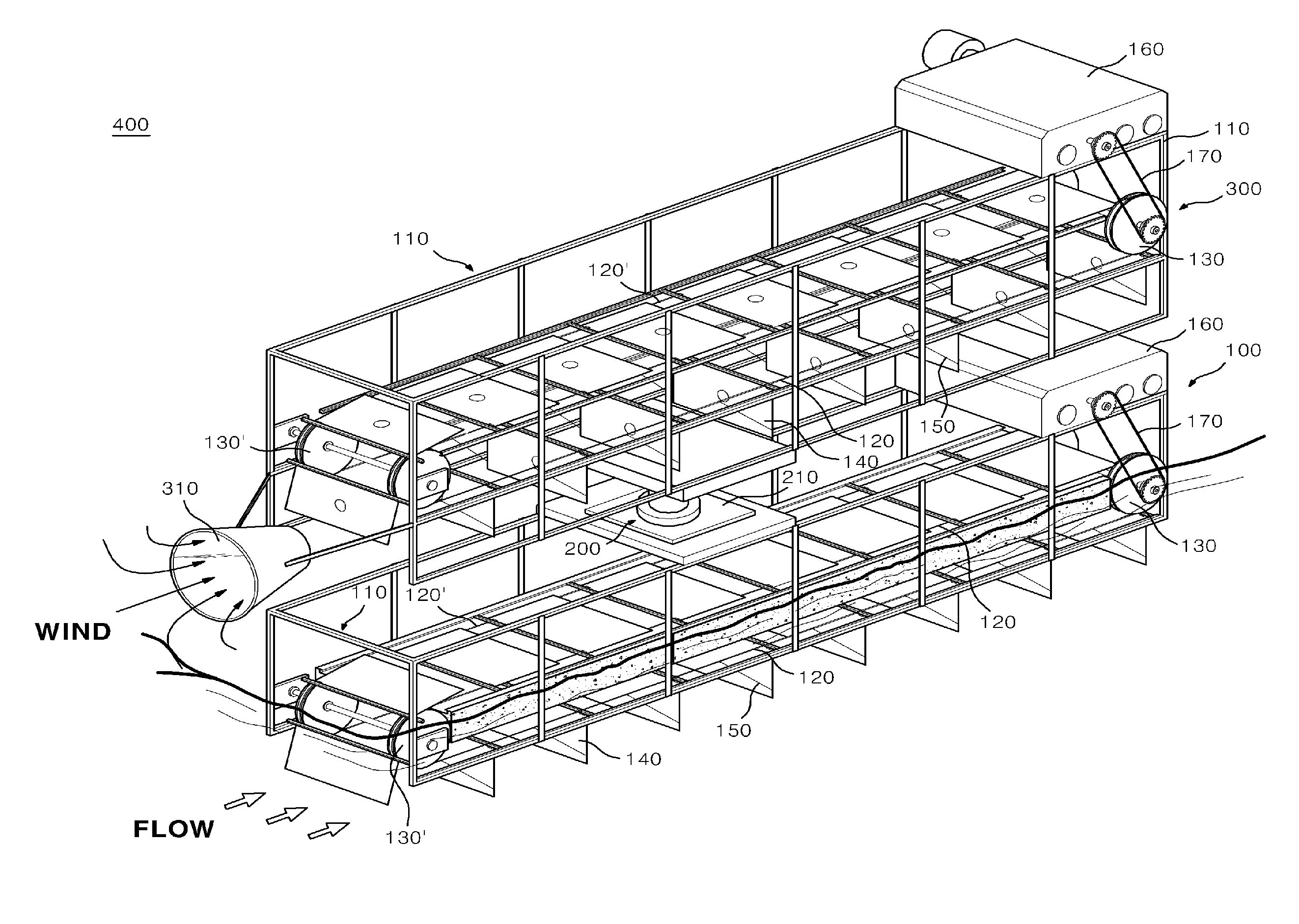
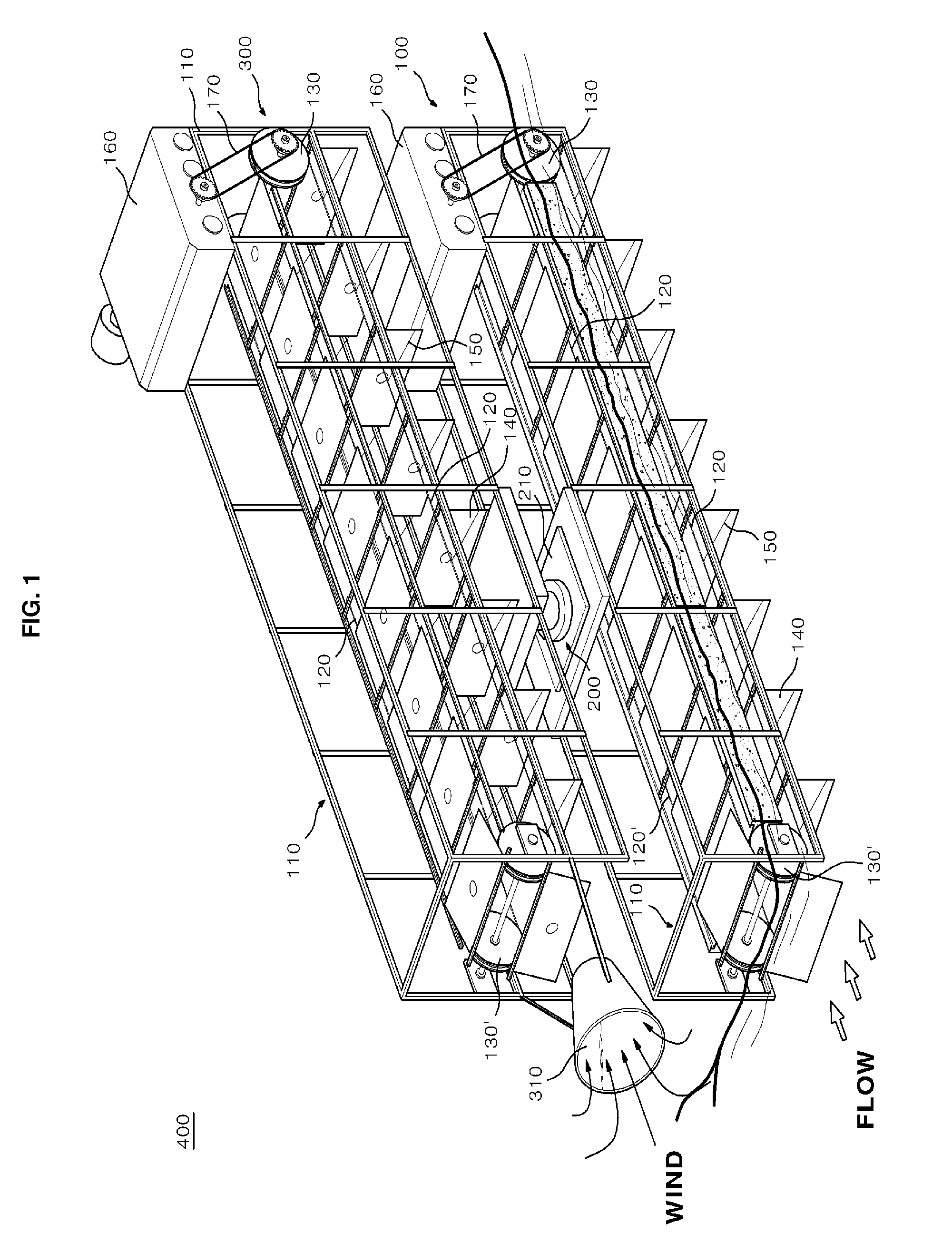
[0041]FIG. 1 is a perspective view showing a wind and water power generator ship according to a preferred embodiment of the present invention.

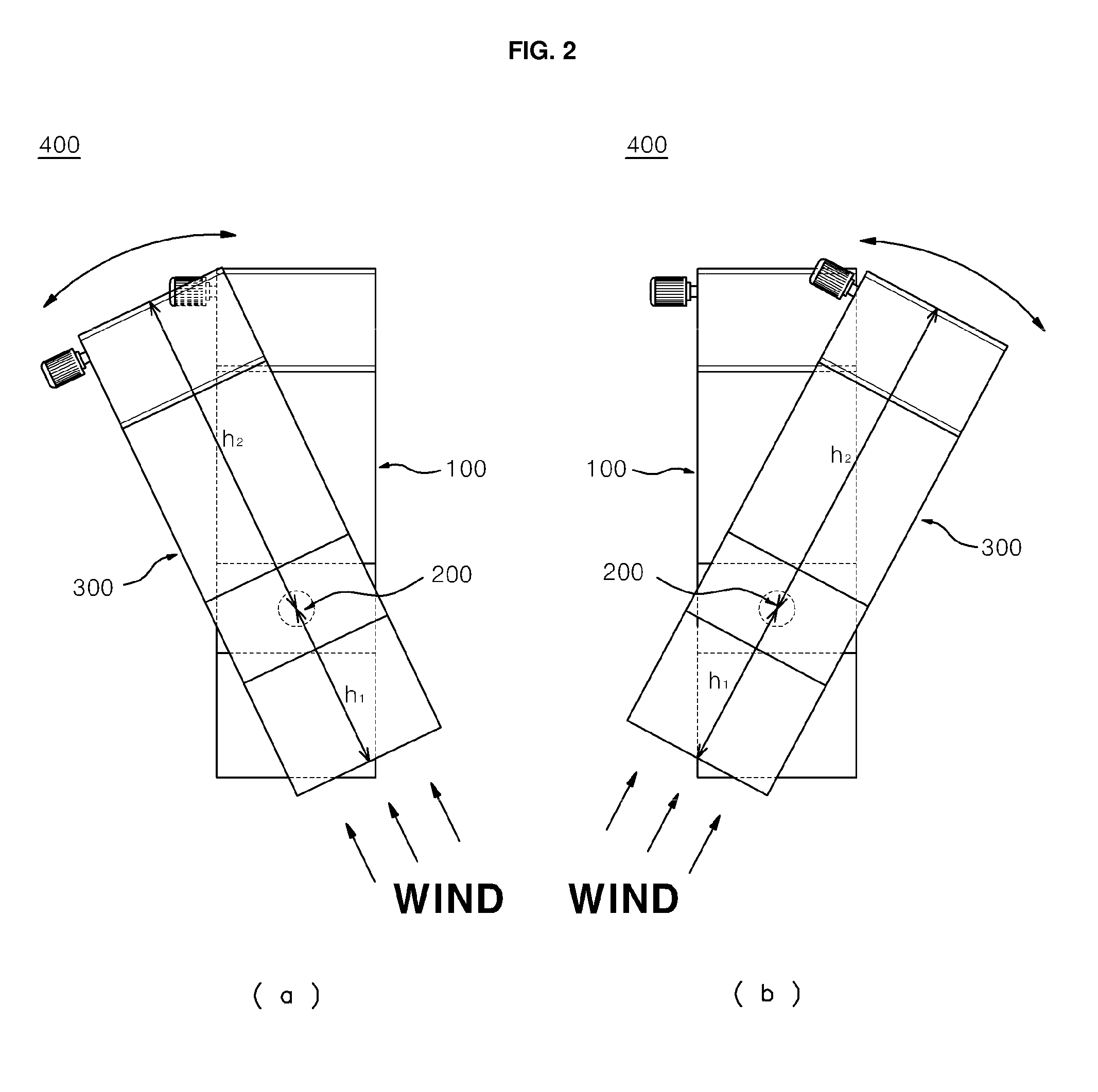
[0042]As shown in the figure, the present invention 400 generally includes a waterpower generation unit 100, a center shaft 200 and a wind power generation unit 300.

[0043]A description will be given first of the waterpower generation unit 100.

[0044]The waterpower generation unit 100 generates electricity using the difference between the ebb and the flow of the tides, and is provided with a buoyant body (not shown) that produces buoyancy, which enables the waterpower generation unit 100 to float on water.

[0045]In more detail, the waterpower generation unit 100 includes a support body 110, which defines the outer shape of the waterpower generation unit 100; a pair of drive rollers 130 and 130′, ...


PUM


Abstract

A wind and water power generator ship. A waterpower generation unit generates electricity using a difference between the ebb and the flow of the tides, and is provided with a buoyant body that produces buoyancy, which enables the waterpower generation unit to float on water. A center shaft is mounted on a base on an upper end of the waterpower generation unit, and is rotatably supported by a bearing. A wind power generation unit generates electricity using wind power, is provided on an upper end of the center shaft, and is rotatable depending on a direction of wind. The distance from a front end of the wind power generation unit to the center shaft is shorter than the distance from the center shaft to a rear end of the wind power generation unit.

Description

REFERENCE TO RELATED APPLICATIONS[0001]This is a continuation of pending International Patent Application PCT / KR2010 / 005295 filed on Aug. 12, 2010, which designates the United States and claims priority of Korean Patent Application No. 10-2010-0061144 filed on Jun. 28, 2010, the entire contents of which are incorporated herein by reference.FIELD OF THE INVENTION[0002]The present invention relates, in general, to a wind and water power generator ship and, more particularly, to a wind and water power generator ship that cruises by supplying self-generated electric power using wind and water power.BACKGROUND OF THE INVENTION[0003]In general, methods of generating electricity using the power of nature include waterpower generation, wind power generation, thermal power generation, etc.[0004]Among these, a number of waterpower generation apparatuses, which generate electricity using the velocity of running water in a sea area where the velocity of the water is fast because of the differen...

Claims


Application Information

Patent Timeline
Patent Type & Authority Patents(United States)
IPC IPC(8): H02P9/04
CPCB63H21/20F03B13/264F03B17/066F03D5/02B63B2035/446B63B2035/4466F05B2210/18F05B2240/93Y02E10/70Y02E10/28Y02E10/725Y02E10/30Y02E10/20Y02E10/72
Inventor KIM, YEONG-SAENGLEE, DAE-HEE
Owner INJE UNIV IND ACADEMIC COOP FOUND
Why Eureka
Try Eureka