Wireless positioning approach using time-delay of signals with a known transmission pattern

a technology of transmission pattern and signal delay, applied in direction finders using radio waves, instruments, sport apparatus, etc., can solve the problems of direct line of sight and cannot work in an indoor environment, limited range of ir, and direct line of sight requirements for ir

Inactive Publication Date: 2013-01-01
GOLBA LLC
View PDF80 Cites 90 Cited by
  • Summary
  • Abstract
  • Description
  • Claims
  • Application Information

AI Technical Summary

Benefits of technology

[0007]Some embodiments employ a known Radio Frequency (RF) transmission pattern to locate a receiver object. As the signal travels between a transmitter and a receiver, the time delay between the two is calculated. By repeating this process with different known coordinate transmitters it is possible to process the time delay information and calculate the unknown position coordinates of the receiver. This calculated position can then be used for location-based services, gaming consoles, and hand gesture recognition systems. The method can be applied to any system that uses a known transmission pattern such as Bluetooth®, Wireless Local Area Network (WLAN), cellular (e.g., 2G, 3G, 4G), Worldwide Interoperability for Microwave Access (WiMax), HD Radio™, Ultra-wideband (UWB), ZigBee, Radio-Frequency Identification (RFID), and 60 GHz standards. This method is low-cost since it can use existing standards and infrastructure. The method is also complementary to GPS since it works in indoor locations, tunnels, and urban canyons where GPS signals may be weak and / or multipath issues could be present. The method is also complementary or instead of cell tower triangulation methods using RF signals since the method works in indoor locations, tunnels, and any area where cellular (i.e., licensed wireless) signals may be weak and / or multipath issues could be present.

Problems solved by technology

GPS systems, however, require direct line of sight and do not work in an indoor environment.
The active badge system uses infrared (IR) technology but it has several limitations such as limited range of IR, direct line-of-sight requirements for IR, and the high-cost of installation of a dedicated system just for object tracking.
Again, this system was a dedicated system dedicated to object and people tracking and was not commercially successful because it required installation of a new infrastructure.
However, these methods provide poor indoor positioning accuracy because RF signal amplitude is greatly affected by metal objects, reflective surfaces, multipath, dead-spots, noise and interference.
Cell tower triangulation is limited in accuracy and reliability because of the coarse number of cell towers and multipath issues.
Their approach does not work in indoor situations where GPS signals are weak or not present.
These methods also require time synchronization and prior knowledge of the position of cellular base-stations.

Method used


Image

  • Wireless positioning approach using time-delay of signals with a known transmission pattern
  • Wireless positioning approach using time-delay of signals with a known transmission pattern
  • Wireless positioning approach using time-delay of signals with a known transmission pattern

Examples


Embodiment Construction

[0032]In the following detailed description of the invention, numerous details, examples, and embodiments of the invention are set forth and described. However, it will be clear and apparent to one skilled in the art that the invention is not limited to the embodiments set forth and that the invention may be practiced without some of the specific details and examples discussed.

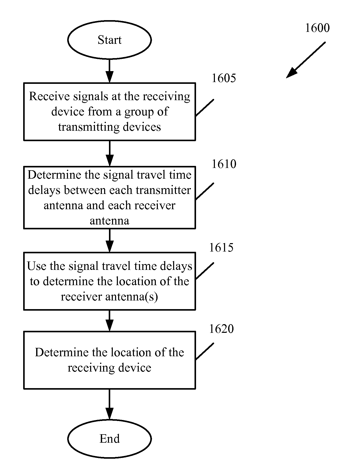
[0033]Some embodiments provide methods and systems that employ a known Radio Frequency (RF) transmission pattern to locate a receiver object. As the signal travels between a transmitter and a receiver the system calculates the time delay between the two. By repeating this process with different known coordinate transmitters it is possible to process the time delay information and calculate the unknown position coordinates of the receiver. This calculated position can then be used for location-based services, gaming consoles, and hand gesture recognition systems. The method can be applied to any system that use...


PUM


Abstract

A method of determining the location of a mobile device is provided. The method receives a signal with a known radio transmission pattern at the mobile device from each of several transmitting devices. The method correlates each received signal with a corresponding signal that has a same known radio transmission pattern to determine the time the signal traveled between the corresponding transmitting device and the mobile device. The method determines the location of the mobile device based on the time the signal travelled between the corresponding transmitting device and the mobile device. In some embodiments, determining the location of the mobile device does not require calculating a distance between the mobile device and any of the transmitting devices. In some embodiments determining the location of the mobile device includes solving a function that is dependent on the time the signals traveled between each corresponding transmitting device and the mobile device.

Description

CLAIM OF BENEFIT TO PRIOR APPLICATIONS[0001]The present Application is a continuation-in-part of and claims priority to U.S. patent application Ser. No. 12 / 059,558, entitled “Methods and Systems for Determining the Location of an Electronic Device”, filed Mar. 31, 2008, published as U.S. Patent Publication No. 2009-0243932 A1, and now issued as U.S. Pat. No. 7,800,541. The present application also claims the benefit of U.S. Provisional Application 61 / 224,347, entitled “Method and System for Determining the Position of a Mobile Station,” filed Jul. 9, 2009. The present application also claims the benefit of U.S. Provisional Application 61 / 231,905, entitled “Method and System for Determining the Position of a Mobile Station,” filed Aug. 6, 2009. The contents of U.S. Patent Publication No. 2009-0243932 A1, now issued as U.S. Pat. No. 7,800,541, U.S. Provisional Application 61 / 224,347, and U.S. Provisional application 61 / 231,905 are hereby incorporated by reference.BACKGROUND[0002]Locat...

Claims


Application Information

Patent Timeline
Patent Type & Authority Patents(United States)
IPC IPC(8): G01S3/02
CPCG01S5/0263H04W24/00G01S5/14G01S5/0289H04W4/025A63F13/216A63F13/235G06F3/017H04L5/0055H04W64/00
Inventor MOSHFEGHI, MEHRAN
Owner GOLBA LLC
Why Eureka
Try Eureka