Portable terminal and antenna module thereof for receiving broadcast signal

a technology for broadcast signals and portable terminals, applied in the structural forms of loop antennas, resonant antennas, ferromagnetic cores, etc., can solve the problems of antennas having a relatively long physical length, implementation of radio functionality, and the outward appearance of externally exposed antennas in portable terminals, etc., to enhance the aesthetic effect of outer appearan

Inactive Publication Date: 2013-01-01
LG ELECTRONICS INC
View PDF10 Cites 10 Cited by
  • Summary
  • Abstract
  • Description
  • Claims
  • Application Information

AI Technical Summary

Benefits of technology

[0011]Therefore, an object of an embodiment of the present invention is to enhance an aesthetic effect of an outer appearance of a portable terminal by installing a broadcast receiving antenna inside the portable terminal having a spatial limitation.
[0012]To achieve these and other advantages and in accordance with this and other purposes of the present invention, as embodied and broadly described herein, there is provided a portable terminal including, a terminal case, and a antenna module installed in the terminal case, and configured to receive a broadcast band, wherein the antenna module includes a chip antenna having a dielectric chip and a conductor, the conductor being patterned on the dielectric chip so as to define a physical length of the chip antenna that enables the chip antenna to operate within the broadcast band, and a conductive plate connected to the chip antenna, and configured to have an area on which a main radiation of the antenna module occurs. A physical length of the broadcast receiving antenna can be reduced as short as possible by employing the chip antenna. Accordingly, the chip antenna facilitates making the antenna module and the portable terminal smaller in size. Also, the chip antenna is configured to lead a main radiation on the conductive plate, thereby increasing radio reception quality and improving radio performance.
[0013]In one embodiment of the present invention, the conductive plate may be integrally formed with the chip antenna to form one body. The conductive plate and the chip antenna may be fabricated by a single process, whereby the antenna module may be handled easily and assembly of the portable terminal is improved. The conductive plate may be configured in a form of a flexible plate such that the conductive plate can reduce or prevent an increase in a thickness of the antenna module, and allow the antenna module to be flexibly engaged with a particular space within the terminal case.
[0016]In one embodiment of the present invention, the terminal case may have a side surface on an edge portion thereof, and the antenna may be disposed inside a recess in the side surface of the terminal case. Hence, the interference of the antenna module with other components within the terminal case can be minimized and radio reception quality can be improved.
[0017]In one embodiment of the present invention, the dielectric chip may have a relative permittivity equal to or greater than 1.0, and also have a relative permeability equal to or greater than 1.0. Accordingly, the dielectric chip with the permittivity and the permeability can effectively reduce the physical length of the antenna module.

Problems solved by technology

An antenna installed in the portable terminal was originally developed to be mounted to be externally exposed, but the use of internal antennas has increased, consideration of the outward appearance of the externally exposed antenna in portable terminal has become an issue.
However, configurations of internal antennas cause a problem in implementation of radio functionality.
In particular, a broadcast band uses longer waves than a mobile communication band, which causes an antenna to have a relatively long physical length, whereby a degradation of reception quality may be caused when the antenna of a relatively short physical length is installed in the portable terminal.
However, in this case, such an antenna may detrimentally affect an aesthetic of the outer appearance of the portable terminal and additionally be subjected to being damaged or lost.
Furthermore, when the earphone cable is used as the antenna, users may find difficult to view (watch) or listen to broadcasts through a loud speaker disposed in the portable terminal having the loose earphone cables.

Method used


Image

  • Portable terminal and antenna module thereof for receiving broadcast signal
  • Portable terminal and antenna module thereof for receiving broadcast signal
  • Portable terminal and antenna module thereof for receiving broadcast signal

Examples


Embodiment Construction

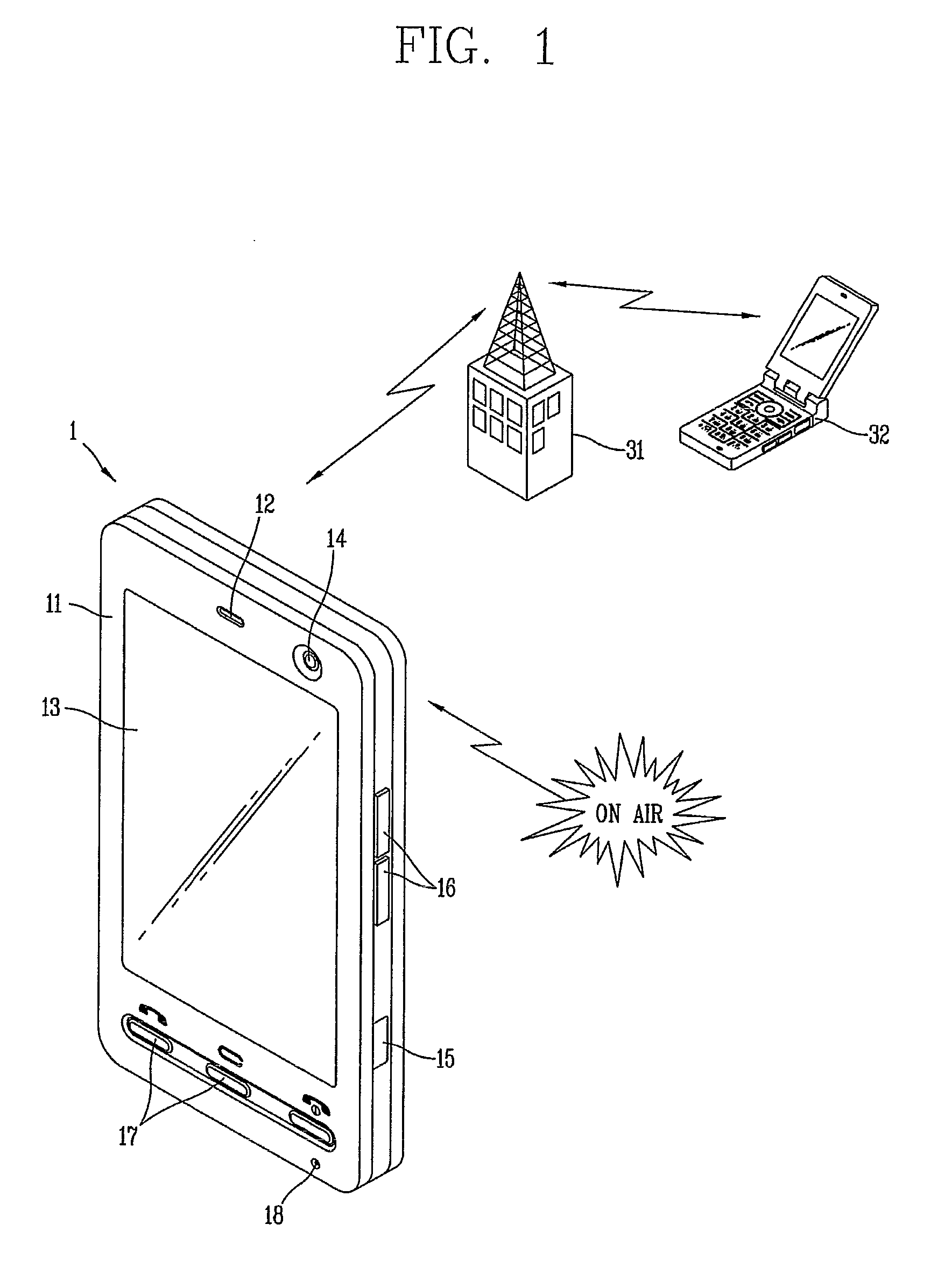
[0030]Description will now be given in detail to a portable terminal according to embodiments of the present invention, with reference to the accompanying drawings. FIG. 1 is a schematic view showing a portable terminal and its operating environment in accordance with an embodiment of the present invention. As shown in FIG. 1, a portable terminal 1 forms a wireless (radio) network together with another terminal 32 removed from the portable terminal 1, and a peripheral base station 31. Such a portable terminal 1 allows wireless audio / video or text communications with the another terminal 32.

[0031]In addition, the portable terminal 1 may be provided with a unit for wirelessly receiving radio broadcasts or TV broadcasts via broadcast signals such that an individual user can watch or listen to broadcast programs of the radio broadcasts or TV broadcasts at any particular place of the user.

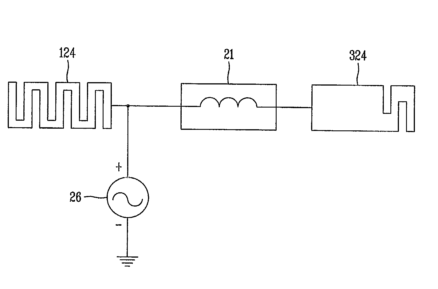
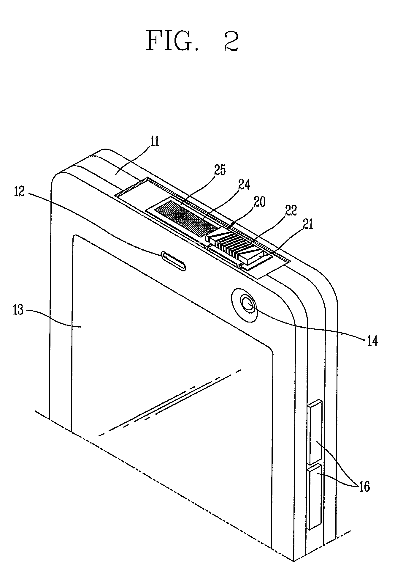
[0032]An antenna for receiving the wireless communications or the broadcasts may be disposed inside ...


PUM


Abstract

A portable terminal with an antenna for receiving broadcast signals, includes an antenna module having a chip antenna patterned on a dielectric chip so as to define a physical length of the antenna module that enables the chip antenna to operate within a broadcast band, and a conductive plate connected to the chip antenna and having an area such that conductive plate leads a main radiation of the antenna module on the broadcast band, whereby the physical length of the antenna module can be reduced as short as possible by employing the chip antenna. Accordingly, the chip antenna facilitates making the antenna module and the portable terminal be smaller in size. Also, the chip antenna is configured to lead a main radiation on the conductive plate, thereby increasing radio reception quality and improving radio performance.

Description

RELATED APPLICATION[0001]This application claims priority to Korean Patent Application No. 10-2008-0044744, filed on May 14, 2008 in the Republic of Korea, which is herein expressly incorporated by reference in its entirety.BACKGROUND OF THE INVENTION[0002]1. Field of the Invention[0003]Embodiments of the present invention relate to a portable terminal with an antenna for receiving broadcast signals.[0004]2. Background of the Invention[0005]A portable terminal is a device that may be carried around and may perform one or more functions such as voice and telephony call communications, input and / or output of information, storing data and the like.[0006]As such functions become more diversified, the portable terminal may support more complicated functions such as capturing still images or video, playing music or video files, playing games, receiving broadcast signals, and the like. By comprehensively and collectively implementing such functions, the portable terminal may be embodied as...

Claims


Application Information

Patent Timeline
Patent Type & Authority Patents(United States)
IPC IPC(8): H01Q1/24
CPCH01Q1/2283H01Q7/08H01Q1/38H01Q1/243H04B1/38
Inventor YI, KYUNG-HACKLEE, DONG-HO
Owner LG ELECTRONICS INC
Why Eureka
Try Eureka