
Multiple pass imaging spectroscopy

a multi-pass imaging and spectroscopy technology, applied in the field of multi-pass imaging spectroscopy, can solve the problem of design being unworkable for multiple passes through a sampl

Active Publication Date: 2013-01-01
SPECTRUM SCI INC (CA)
View PDF3 Cites 7 Cited by
  • Summary
  • Abstract
  • Description
  • Claims
  • Application Information

AI Technical Summary

Problems solved by technology

However, each ray only passes through the sample once; this means that many different rays pass through the same sample region at a large number of differing angles.
Because the radiation is focused only at a single point and is divergent everywhere else, this design is unworkable for multiple passes through a sample.

Method used


Image

  • Multiple pass imaging spectroscopy
  • Multiple pass imaging spectroscopy
  • Multiple pass imaging spectroscopy

Examples


case b

Standard External Reflectance Experiment

Class I

[0037]As in Case A, except that the ray reaching the detector has three components. Each component can be represented by a separate equation. The first component is specular reflectance from the top surface of the sample. The second component is diffuse reflectance consisting of rays scattered and absorbed several times in the sample bulk. Diffuse reflectance is measured by focussing off-specular rays at the detector. The third component, reflection-absorption, is transmitted through the sample suffering absorption as it passes through the sample. This ray reflects off a substrate, and passes through the sample again suffering absorption on the way to the detector. Because the rays pass through the sample twice, the coefficients of the C matrix are 2.0. The relative importance of each component depends upon the sample and experimental conditions.

Case C Standard Internal Reflectance Experiment

Class II

[0038]There are many sample segments ...


PUM

PropertyMeasurementUnit
angle of incidenceaaaaaaaaaa
pressureaaaaaaaaaa
pressureaaaaaaaaaa

Abstract

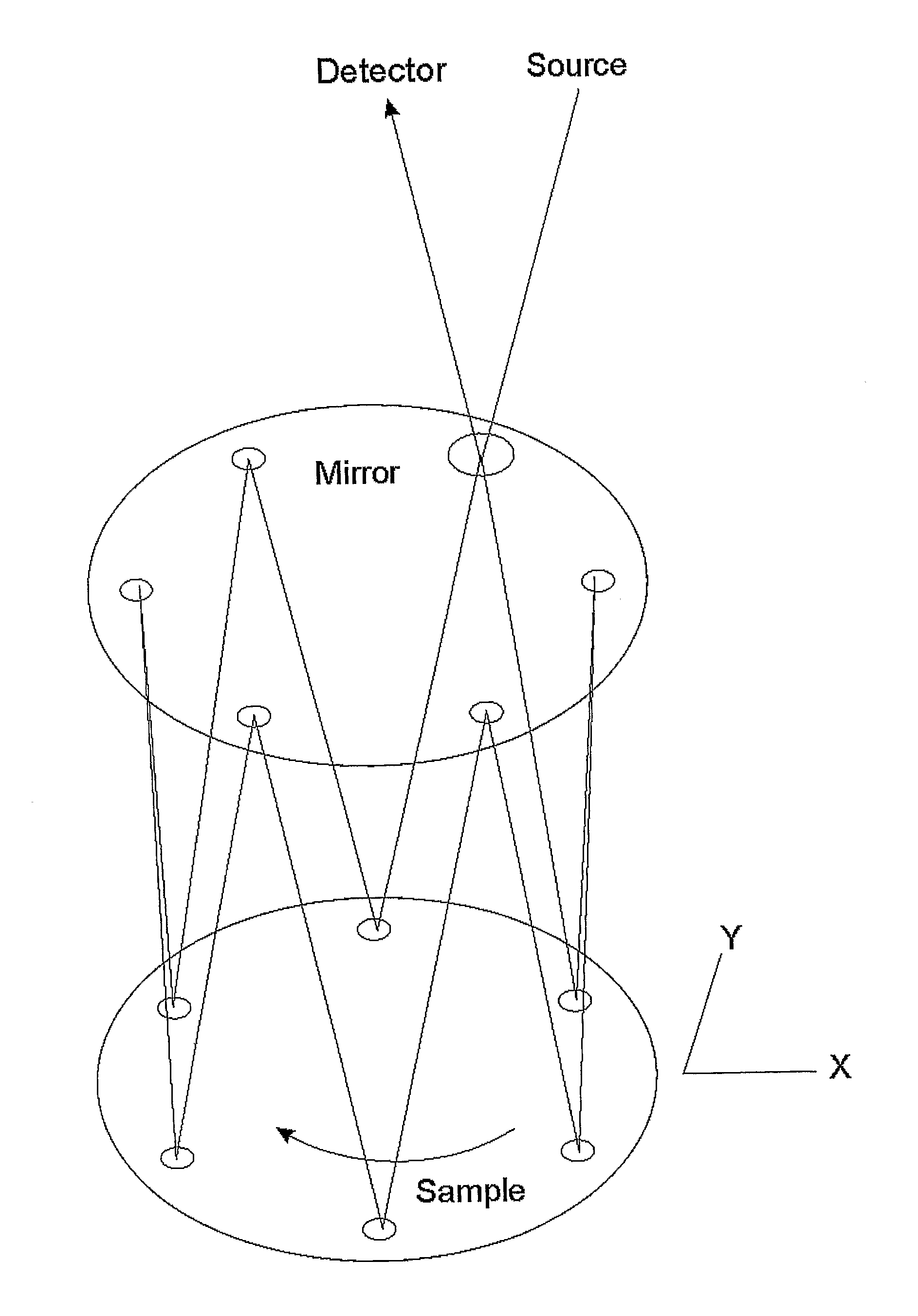
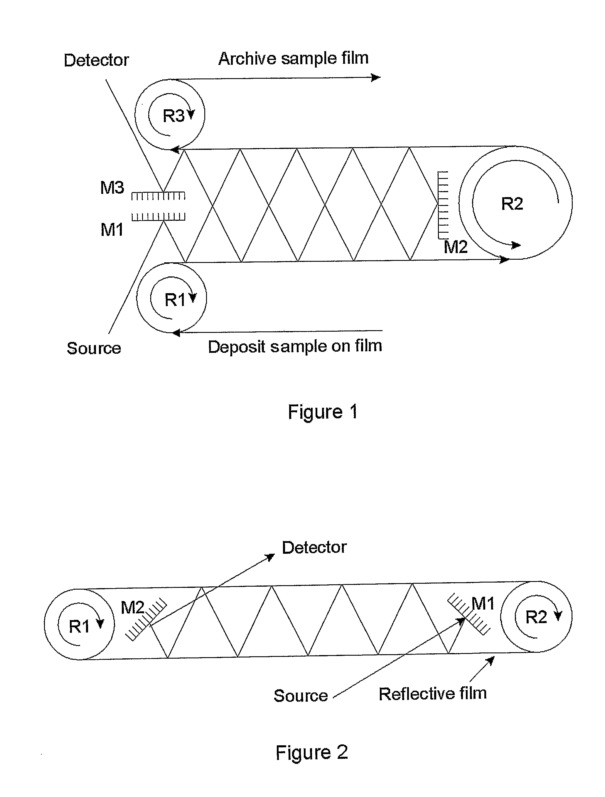
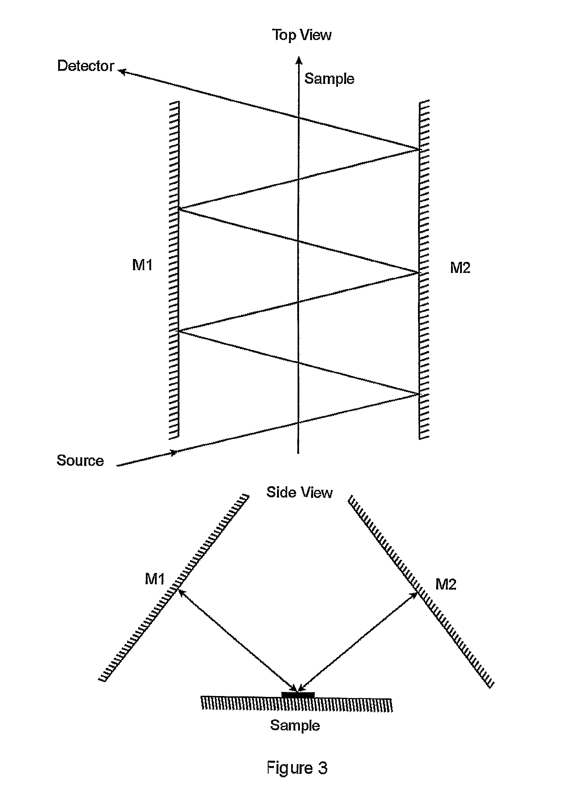
A method of imaging an optically thin sample is described wherein a collimated beam is directed through the sample and then reflected back through the sample one or more times. The beam is then directed toward a detector which collects and analyzes the spatial and spectral composition of the beam. In some embodiments, the detector is a focal plane array with a large number of detector elements. In other embodiments the relative position of a single detector or a small detector array and the sample is altered and the process is repeated, thereby tracing out a large virtual detector array. In either case, the spectral information received by the detector elements can be related, by methods which are elaborated below, to information about the spatial distribution of absorption in the sample.

Description

PRIOR APPLICATION INFORMATION[0001]This application claims the benefit of the filing date of U.S. Provisional Application 60 / 543,918, filed Feb. 13, 2004.BACKGROUND OF THE INVENTION[0002]US Patent Application 20020101587 teaches an optical system that can determine the spectra of all points in a two-dimensional scene. However, each ray only passes through the sample once; this means that many different rays pass through the same sample region at a large number of differing angles.[0003]U.S. Pat. No. 5,818,046 teaches a combination of mid-infrared transparent elements with new element geometry, new design of the optics and a new radiation path. Specifically, radiation emerges from an IR microscope objective and is then reflected at the sample before being reflected either back to the microscope objective or to a detector. Because the radiation is focused only at a single point and is divergent everywhere else, this design is unworkable for multiple passes through a sample.[0004]U.S. ...

Claims


Application Information

Patent Timeline
Patent Type & Authority Patents(United States)
IPC IPC(8): G01N21/47G01N21/00G01N21/25G01N21/31G01N21/55G01N21/86
CPCG01N21/552G01N21/86
Inventor PRYSTUPA, DAVID
Owner SPECTRUM SCI INC (CA)
Learn More