Method and apparatus for laser-based remote methane leak detection

a laser-based, remote methane technology, applied in the field of leak detection, can solve the problems of a few seconds detection delay, low sensitivity, and difficulty in detecting low gas concentrations,

Active Publication Date: 2006-07-11
HEATH CONSULTANTS
View PDF10 Cites 113 Cited by
  • Summary
  • Abstract
  • Description
  • Claims
  • Application Information

AI Technical Summary

Benefits of technology

[0028]Another object of the invention is to provide a method for optical leak detection and an optical detector therefor ...

Problems solved by technology

They are generally unable to detect gas mixtures much below the lower combustible concentration limit, and thus they have generally low sensitivity and do not readily detect low gas concentrations.
There is generally a detection delay of a few seconds associated with the time required to draw the gas sample into the measurement chamber.
However, the short open probe must still be immersed in the leak plume for detection to occur.
The procedure may be arduous, particularly when access to private property is involved.
Obstacles such as fences and dogs can be problematic.
Unless the leak is located close to the right-of-way or a fortuitous breeze exists, the plume must generally be large in order to reach the right of way and hence is likely to be of lower concentration and more difficult to detect.
These larger emissions may cause major vegetation discoloration or disruptions to the pipe cover.
During the past decade, however, the technology has developed primarily because of the advent of reliable monochromatic near-infrared (1.2–2.5 μm) diode lasers that operate continuously and unattended at room temperature without cooling by liquid nitrogen.
Otherwise, the user may become crazed by a continuous cannonade of cacophonous tones.
The frequency of the tone changes from sample to sample, causing the user to perceive noise.
Because the user is forced to carefully listen to discordant tones throughout the entire survey, surveying can be particularly fatiguing for the user.
Additionally, there are several characteristics of stand-off detection that hamper the user's ability to distinguish background methane from methane result...

Method used


Image

  • Method and apparatus for laser-based remote methane leak detection
  • Method and apparatus for laser-based remote methane leak detection
  • Method and apparatus for laser-based remote methane leak detection

Examples


Embodiment Construction

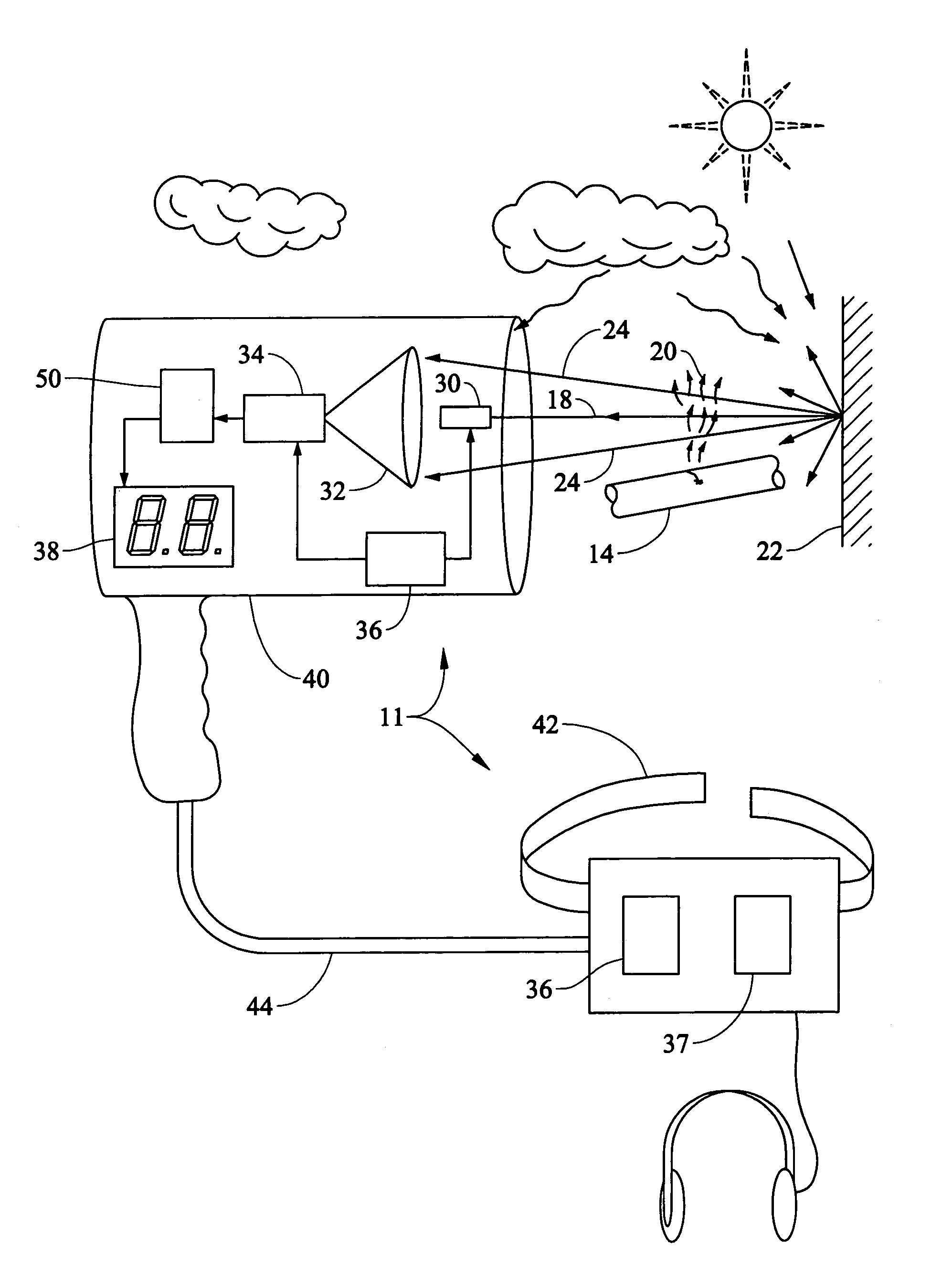
[0046]Referring to FIG. 3, a laser methane detector 11 of the preferred embodiment ideally includes a number of functionally interactive components: a laser emitter subsystem 30 that contains a tunable diode laser source module and electronic modules that synthesize the laser modulation and control signals; an optical detector 32, e.g., a photodiode; a signal processing module 34 which contains the electronic components that extract the absorption signal information from the optical detector's output; a system controller 36; a rechargeable battery pack 37; and a statistical methane detection processor module 50. The laser methane detector is preferably packaged into a two-piece system including a hand-held gun 40 (having the laser 30 and detector 32 (combined into an optical transceiver) and a LCD alphanumeric display 38) and a shoulder or waist-mounted controller / battery pack unit 42. The two sections 40, 42 are preferably connected by an umbilical cable 44 having optical fibers an...


PUM


Abstract

A method and apparatus for remote laser-based detection of gas at levels exceeding natural background levels preferably utilizing wavelength modulated tunable diode laser absorption spectroscopy. In a preferred embodiment, background gas and noise are estimated using statistical moving average and variance calculations. Gas concentration length measurements resulting from the spectroscopy are preferably compared in real-time or near-real-time to the sum of the background and noise estimates and an alarm limit to detect gas presence of concern. Gas levels exceeding this detection threshold are preferably indicated by a prolonged output tone with a pitch indicative of the magnitude of the gas measurement, and gas levels below the detection threshold are preferably indicated by silence.

Description

BACKGROUND OF THE INVENTION[0001]1. Field of the Invention[0002]This invention relates generally to leak detection and specifically to detection of methane gas, particularly for use in conducting routine surveys of natural gas utility pipelines.[0003]2. Description of the Prior Art[0004]Natural gas utility companies operate approximately 61 million customer gas meters in the United States alone, supplied by over one million miles of pipeline, 17 hundred transmission stations and 17 thousand compressors. To maintain security and integrity of this vast distribution system and to comply with regulatory requirements, gas pipelines are subject to regular inspections to detect leaks. Routine periodic leak surveys are typically accomplished by a walking survey, a mobile survey or an aerial survey, and it is estimated that the natural gas distribution and transmission industry spends over $300 million annually to survey the pipeline network for leaks. Because varying trace levels of methane...

Claims


Application Information

Patent Timeline
IPC IPC(8): G01N21/61G01F1/66
CPCG01F23/14G01M3/20G01N21/39G01M3/38G01M3/22
Inventor RUTHERFORD, JAMES M.
Owner HEATH CONSULTANTS
Why Eureka
Try Eureka