Parameterized configuration for a programmable logic device

a programmable logic and configuration technology, applied in the field of parameterized configuration of programmable logic devices, can solve the problems of large implementation time, ineffective run-time hardware generation for most applications, and high computational cost of conventional implementation tools, and achieve the effect of shortening the reconfiguration tim

Active Publication Date: 2013-01-01
UNIV GENT
View PDF16 Cites 9 Cited by
  • Summary
  • Abstract
  • Description
  • Claims
  • Application Information

AI Technical Summary

Benefits of technology

[0007]An advantage of embodiments of the present invention is that it provides a possibility for generating a parameterized configuration for a programmable logic device (either a part thereof or complete configuration) wherein the run-time part of the hardware generation time is much shorter compared to conventional methods. Another advantage of embodiments of the present invention is that it provides a shorter reconfiguration time than conventional methods. Each of these advantages allow the run-time hardware generation to be applicable for a large class of applications.
[0008]It is an advantage of embodiments of the present invention that no full configuration data is to be provided or stored upfront for each possible configuration to be used for the programmable logic device, for allowing these configurations to be implemented with the programmable logic device.
[0022]According to another preferred embodiment of the invention, the step of mapping the tunable circuit to the programmable logic device comprises the steps of generating a master configuration for configuring the programmable logic device at startup, and evaluating the tuning functions which are used by a configuration manager at run-time. This means that the tunable logic block's functionality is partially implemented by a logic block on the programmable logic device and partially by a tuning function that is evaluated by the configuration manager. Preferably, when a new configuration is needed, the tuning functions are evaluated for the new parameter values resulting in new configuration bits for the programmable logic device's logic blocks. Further, it is preferred that these configuration bits are then written to the configuration memory. Removing the tuning input signals and the associated connections from the tunable circuit results in the regular logic block circuit that needs to be implemented on the programmable logic device. This can be done with conventional place and route tools. After placement and routing all configuration bits can be extracted except those that are expressed by a tuning function, called tunable configuration bits. This enables the generation of the master configuration, a configuration wherein the tunable configuration bits are replaced by a dummy value. This master configuration can be used as a template to set the programmable logic device's configuration memory at system startup.
[0026]According to a further preferred embodiment of the invention, the logic block with the at least one data input signal and / or the at least one select input signal is provided as a Look Up Table. Preferably, the data of a Look Up Table (LUT) is provided as a data structure, which is used to replace a run-time computation with a simple look-up operation. This decreases computational time, since retrieving a value of a memory is often faster than undergoing an expensive computation.

Problems solved by technology

However, due to the inherent reconfigurability of static RAM-based FPGAs, this implementation can also be performed on the fly.
However, conventional implementation tools are computationally very expensive which leads to a large implementation time and makes run-time hardware generation useless for most applications.
However, in many applications, subsequent data manipulations only differ in a small set of parameter values.
The overhead involved in generating optimized configurations on the fly with conventional tools is very big.

Method used


Image

  • Parameterized configuration for a programmable logic device
  • Parameterized configuration for a programmable logic device
  • Parameterized configuration for a programmable logic device

Examples


Embodiment Construction

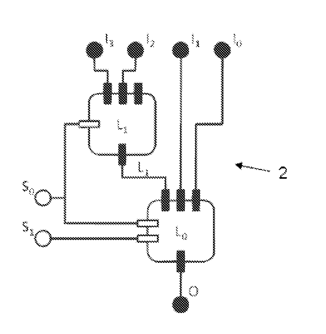
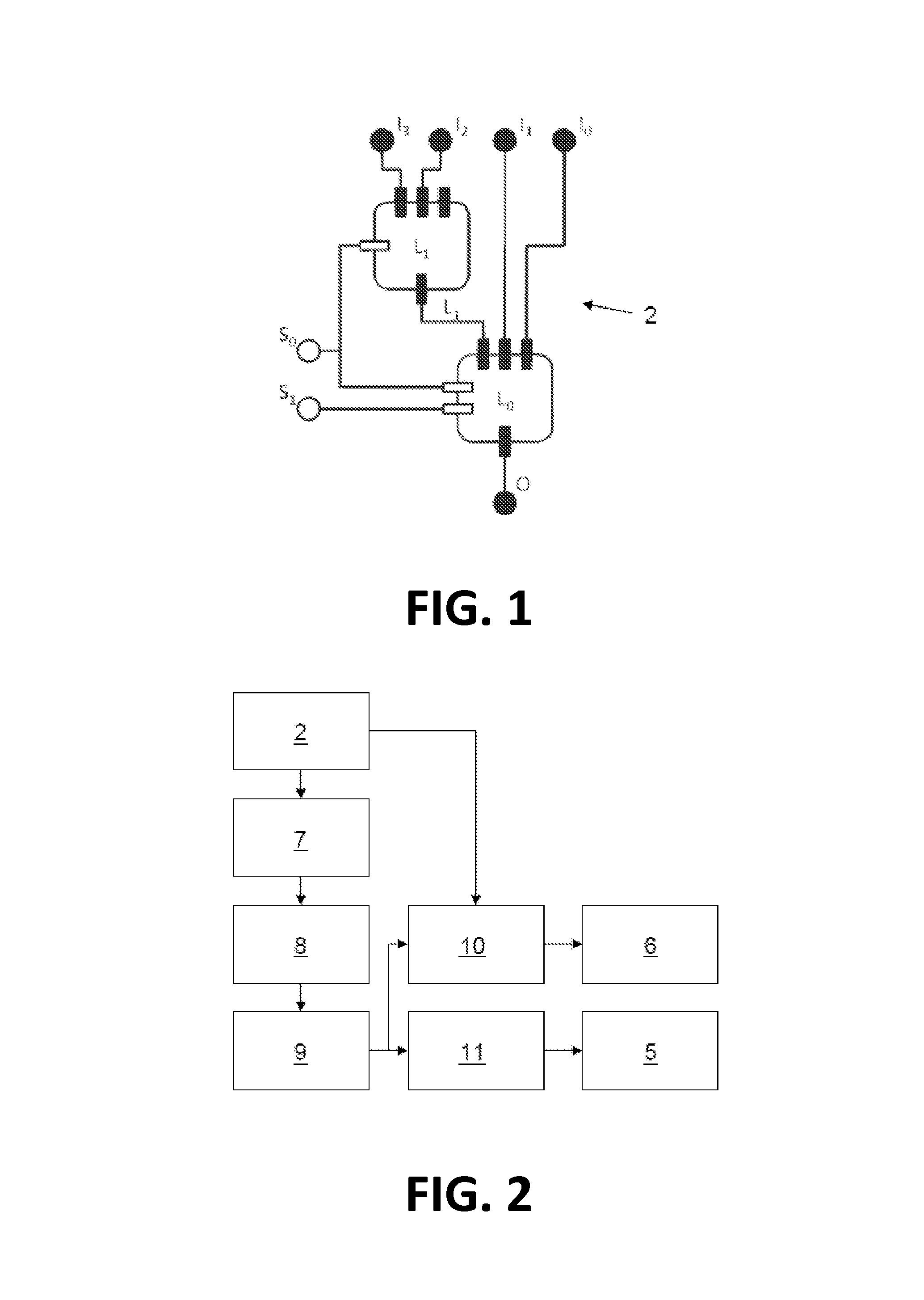
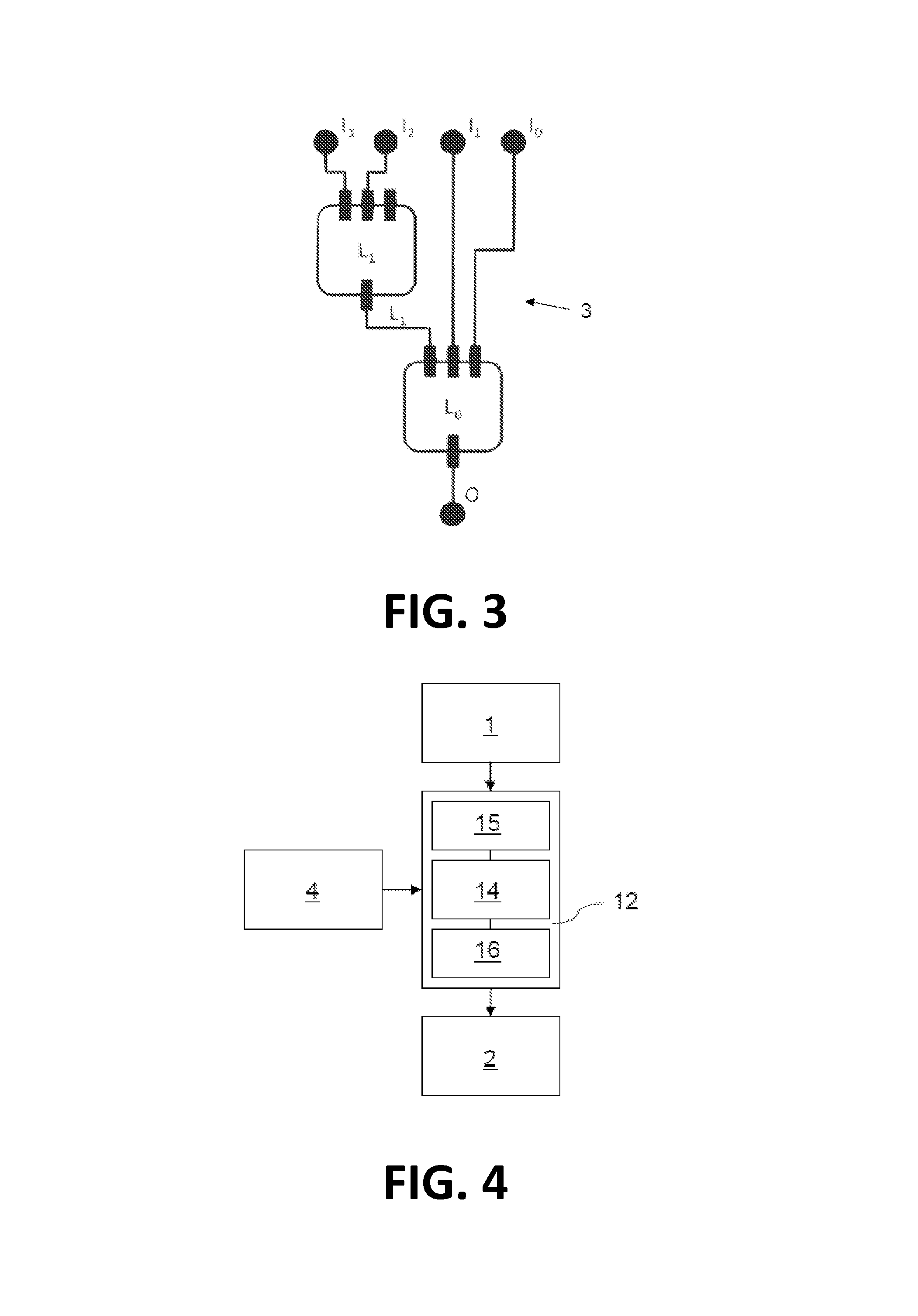
[0051]The present invention will be described with respect to particular embodiments and with reference to certain drawings but the invention is not limited thereto but only by the claims. The drawings described are only schematic and are non-limiting. In the drawings, the size of some of the elements may be exaggerated and not drawn on scale for illustrative purposes. The dimensions and the relative dimensions do not correspond to actual reductions to practice of the invention.

[0052]Furthermore, the terms first, second, third and the like in the description and in the claims, are used for distinguishing between similar elements and not necessarily for describing a sequential or chronological order. It is to be understood that the terms so used are interchangeable under appropriate circumstances and that the embodiments of the invention described herein are capable of operation in other sequences than described or illustrated herein.

[0053]Moreover, the terms top, bottom, over, under...


PUM


Abstract

The invention relates to a method and a tool for generating a parameterized configuration for a Field Programmable Gate Array from a Boolean function, the Boolean function comprising at least one parameter argument, comprising the steps generating at least one tunable logic block from the Boolean function and from at least one parameter argument, and mapping the at least one tunable logic block to the Field Programmable Gate Array. This is advantageous since a parameterized configuration can be generated faster than with conventional tools.

Description

[0001]The invention relates to combinational logic synthesis and in particular to a computer based method and apparatus for generating a parameterized part- or complete configuration for a programmable logic device from any digital circuit and a set of parameter inputs which is a subset of the circuit's inputs and to corresponding devices. The invention also relates to a method and apparatus for generating a part- or complete parameterized configuration for a programmable logic device from a Boolean function and a set of parameters which is a subset of the function's arguments and to corresponding devices.TECHNICAL BACKGROUND[0002]Programmable logic devices (PLDs), such as Field Programmable Gate Arrays (FPGAs), are generally used as building blocks in creating electronic circuit designs. A programmable logic device is a hardware component whose functionality can be configured.[0003]A logic design is an abstract description of functionality that, when implemented in hardware, perfor...

Claims


Application Information

Patent Timeline
Patent Type & Authority Patents(United States)
IPC IPC(8): G06F17/50
CPCG06F17/5054G06F30/34
Inventor BRUNEEL, KAREL
Owner UNIV GENT
Why Eureka
Try Eureka