Impact reduction system

a technology of impact reduction and compression, applied in the direction of shock absorbers, eye treatment, machine supports, etc., can solve the problems of compressing and collapsing of the first layer of the implant, and achieve the effects of reducing the impact resistance of the implant, preventing puncture, and facilitating inflation or deflation

Active Publication Date: 2013-01-08
IARMORHLDG INC +1
View PDF30 Cites 16 Cited by
  • Summary
  • Abstract
  • Description
  • Claims
  • Application Information

AI Technical Summary

Benefits of technology

[0011]One aspect of the present invention provides pads of increased flexibility and decreased weight by constructing the pads of two thin layers of low density polyethylene material, where at least one layer has a series of dimples or impressions formed therein. The first layer of polyethylene may be configured to be positioned proximate to a human body. This first layer may define dimples or protrusions extending outwardly away from the body. The second layer may be configured to be positioned over the top of the first layer in a position removed from the body. This second layer may be constructed of low density polyethylene material formed into a flat sheet with no dimples. Alternatively, the second layer may define dimples that extend toward and come in close proximity to the dimples of the first layer. The second layer may be positioned opposite the first layer with the dimples of the first layer protruding in a direction toward the second layer or with dimples on each layer coming into close contact with each other.
[0012]Upon application of an impact force, the layers of the pads disperse the kinetic energy of the impact in at least two ways. First, the low density polyethylene material that makes up the first and second layers dissipates the energy in a broad way, including outside the plane in which the force is applied. Second, the dimples formed in the first layer will compress and collapse against either the flat second layer or a corresponding dimple of the second layer. As the dimples collapse, the kinetic energy that is directed parallel to the center axis of each dimple will be diffused. The majority of the energy will be redirected 360 degrees radially from the apex of the dimples and along the arcs thereof. Moreover, upon collapse of the dimples, some energy will also dissipate in the form of elastic energy, heat, sound, and so forth. Thus, the amount of kinetic energy from the impact that passes through the pad and into the human body is greatly reduced and more broadly dispersed.
[0013]Another aspect of the present invention provides an inflatable bladder configured to be positioned between the first and second layers of the pads. The bladder includes a valve for attachment to a pump or air inflation system. Inflation of the bladder, using the pump, adds a further cushion of air to the device. The air may serve to further dissipate the energy of an impact force beyond that level achieved by the polyethylene layers alone. In addition, additional mechanisms, such as carbon nanotubes, may be added to the pads in order to further dissipate energy.
[0014]Because the dimples of the layers of the present pads dissipate at least a portion of the impact energy, the thickness of the pads can be greatly reduced compared to pads of the prior art. The reduction of thickness of the pads may be further accomplished by including dimples on only one layer of the pads, as shown in FIG. 12, or by staggering the dimples of the two layers so that they are offset, with the apices of the dimples of the first layer corresponding to the voids between the dimples of the second layer, as shown in FIG. 13. The corresponding reduction of thickness of the present pads allows the pads to be lighter weight, less bulky, more flexible, and permit ore freedom of movement than pads of the prior art. Furthermore, the inflatable bladder of the present pads may provide increased protection and allow the user to adjust the level of impact resistance of the pad according to the requirements of the particular user and circumstance.
[0021]In a preferred embodiment, the impact reduction pad may further include nanotubes attached to at least a portion of the pad to increase the impact resistance thereof. The nanotubes may be selected from the group consisting of coiled nanotubes and composite nanotubes. In addition, the pad may include a puncture resistant layer contacting the inflatable portion of the pad to prevent puncture thereof. The puncture resistant layer may be composed of nanotubes. Preferably, the pad may also include a pump configured for releasable attachment to the inflatable portion of the pad to facilitate inflation or deflation thereof.

Problems solved by technology

Second, the dimples formed in the first layer will compress and collapse against either the flat second layer or a corresponding dimple of the second layer.

Method used


Image

  • Impact reduction system
  • Impact reduction system
  • Impact reduction system

Examples


Embodiment Construction

[0037]The foregoing aspects, features, and advantages of the present invention will be further appreciated when considered with reference to the following description of preferred embodiments and accompanying drawings, wherein like reference numerals represent like elements. In describing the preferred embodiments of the invention illustrated in the appended drawings, specific terminology will be used for the sake of clarity. However, the invention is not intended to be limited to the specific terms used, and it is to be understood that each specific term includes equivalents that operate in a similar manner to accomplish a similar purpose.

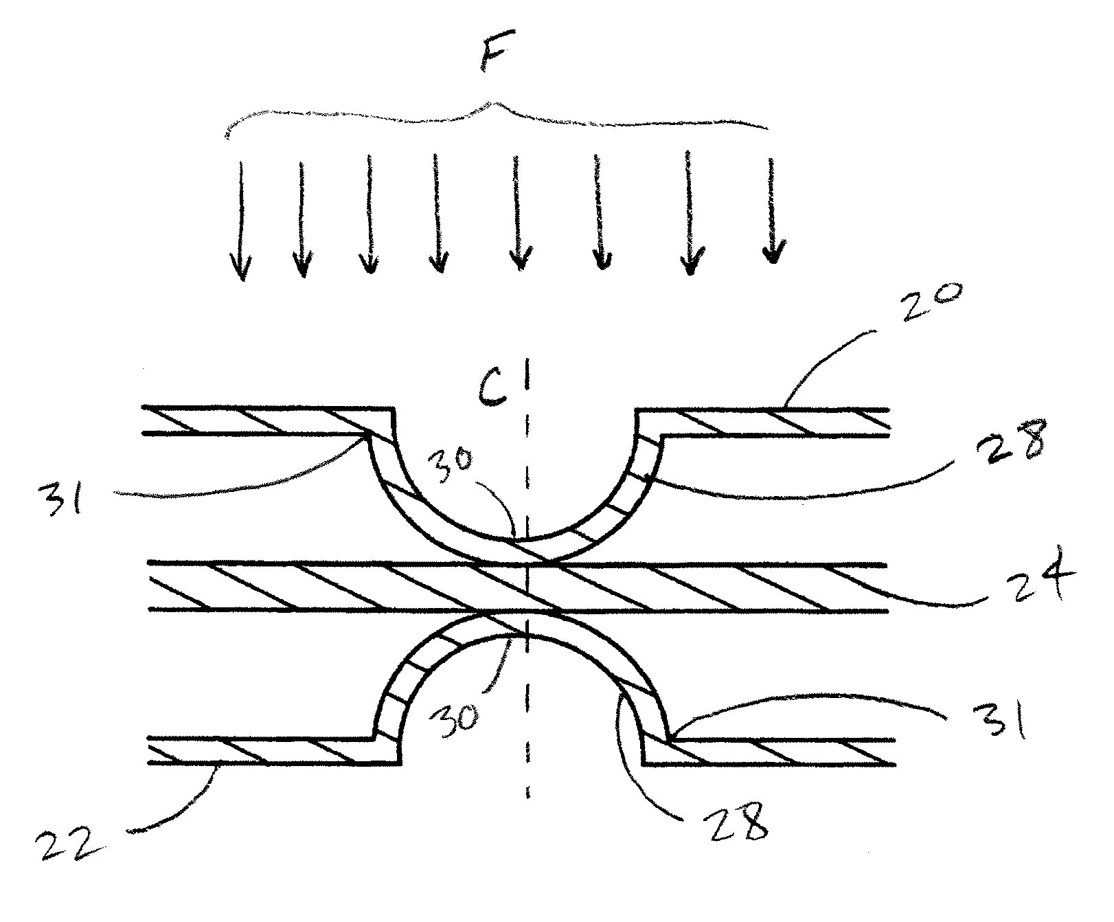
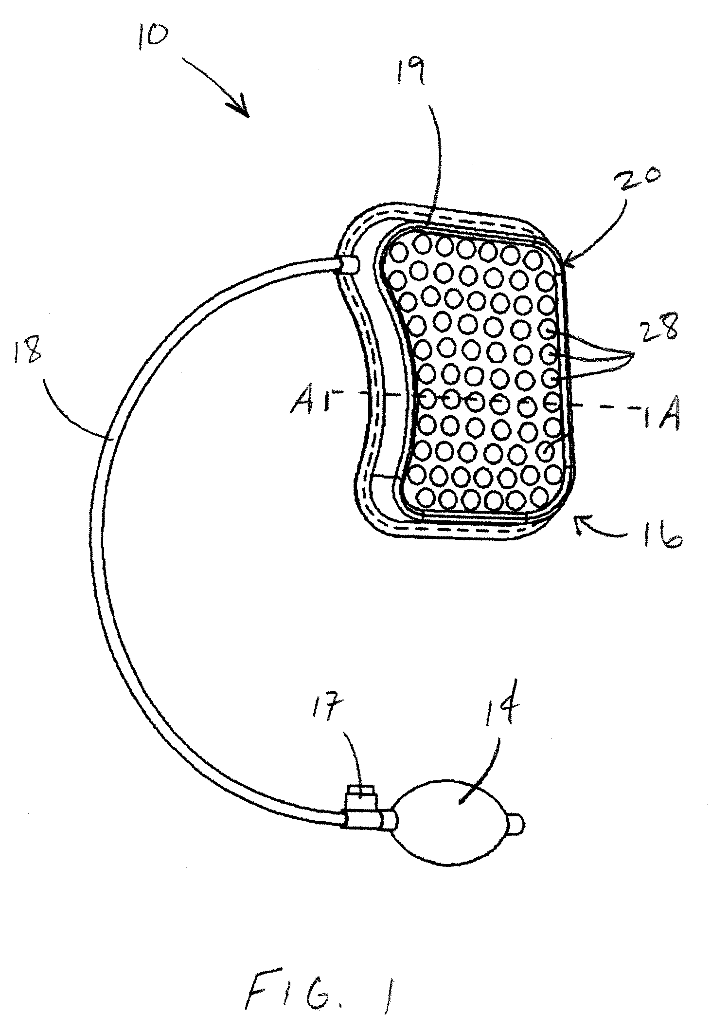
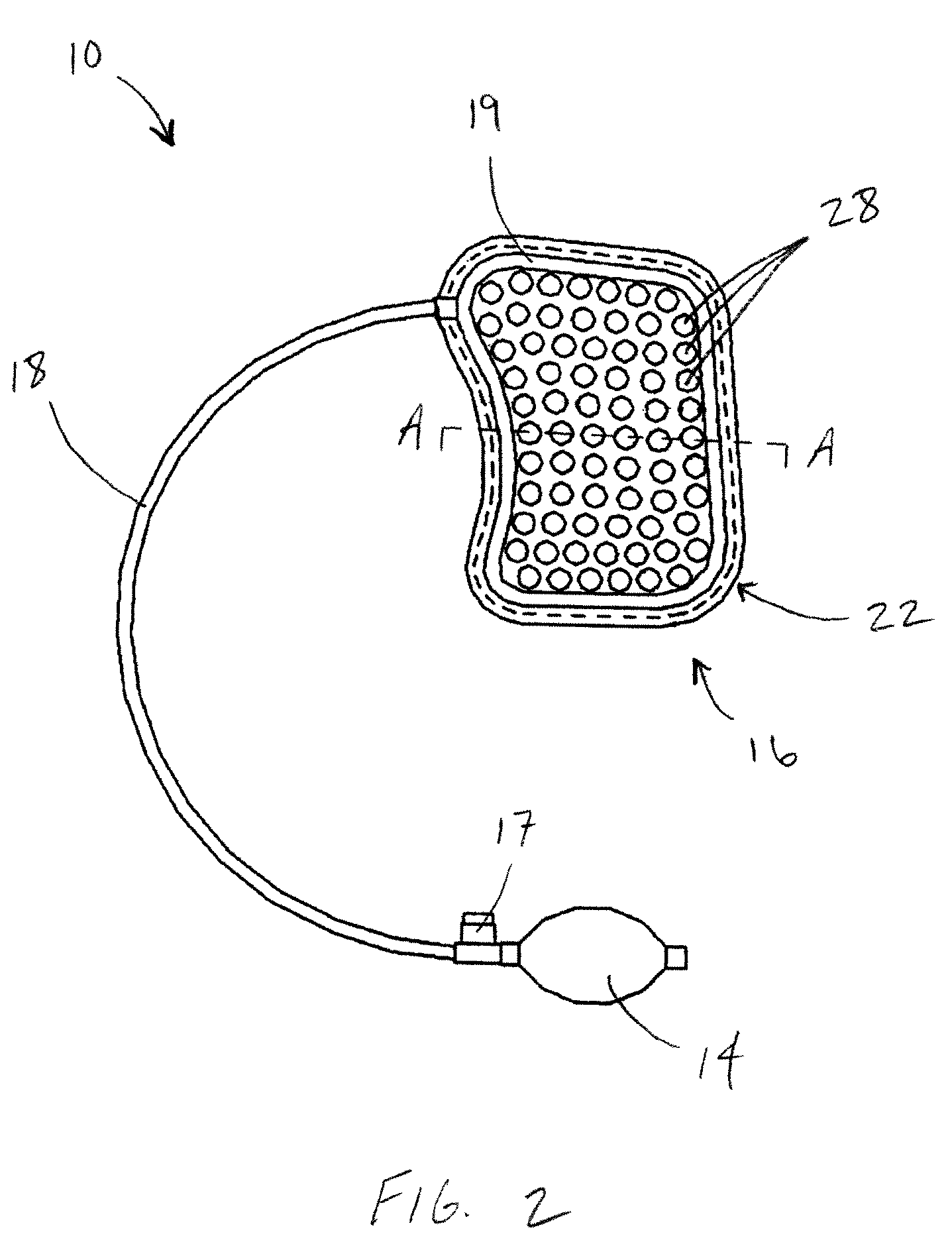
[0038]Referring now to the drawings, FIGS. 1 and 2 show an impact reduction device 10 in accordance with an embodiment of the present technology. The impact reduction device 10 may include a pad 16 formed of two opposing layers, including a back layer 22 and front layer 20. The pad 16 may include one or more ribs 19 to stiffen the pad at its perip...


PUM


Abstract

An impact reduction device including a pad having a first layer and a second layer. At least one of the first and second layers defines at least one impression. The impact reduction device is arranged and configured to at least partially collapse upon application of a force and to regain its shape after removal of the force.

Description

CROSS-REFERENCE TO RELATED APPLICATIONS[0001]This application is a continuation-in-part application of U.S. application Ser. No. 11 / 828,326, filed Jul. 25, 2007 now U.S. Pat. No. 7,917,972, which is hereby incorporated by reference in its entirety.FIELD OF THE INVENTION[0002]The present invention generally relates to devices for absorbing shock. More particularly, the present invention relates to impact reduction devices for use in contact sports, gravity game sports, marksmanship, or other potential contact activities.BACKGROUND OF THE INVENTION[0003]Protective pads are used in a variety of applications to protect the body from injury-causing physical impact. For example, athletes often wear protective pads while playing sports, such as American football, hockey, soccer, gravity game sports, and baseball, among others. In addition, many marksmen wear protective pads while shooting firearms to increase their accuracy and protect their bodies from forces associated with firearm recoi...

Claims


Application Information

Patent Timeline
Patent Type & Authority Patents(United States)
IPC IPC(8): A41D13/00
CPCA41D13/0151A42B3/122F41C23/08
Inventor KRUEGER, WESLEY W. O.
Owner IARMORHLDG INC
Why Eureka
Try Eureka