Waste water pumping device

a technology of waste water and pumping device, which is applied in the direction of gas/liquid distribution and storage, container, using liquid separation agent, etc., can solve the problems of unfavorable service and operation in such developed pumping stations, and significant increase in production costs of new waste water pumping devices

Active Publication Date: 2013-01-08
SZUSTER MIROSLAW +1
View PDF10 Cites 1 Cited by
  • Summary
  • Abstract
  • Description
  • Claims
  • Application Information

AI Technical Summary

Benefits of technology

[0011]The above requirements can be fulfilled by a pumping waste water device located in the by a waste water pumping device placed in the dry tank in form of a manhole well in which the retention part is located in at least one tight retention tank, while the device its...

Problems solved by technology

Nevertheless, the conditions of service and operation in such developed pumping stations have not improved noticeably, while their production costs have risen significantly.
The main disadvantage of this solution is the difficult op...

Method used


Image

  • Waste water pumping device
  • Waste water pumping device
  • Waste water pumping device

Examples


Embodiment Construction

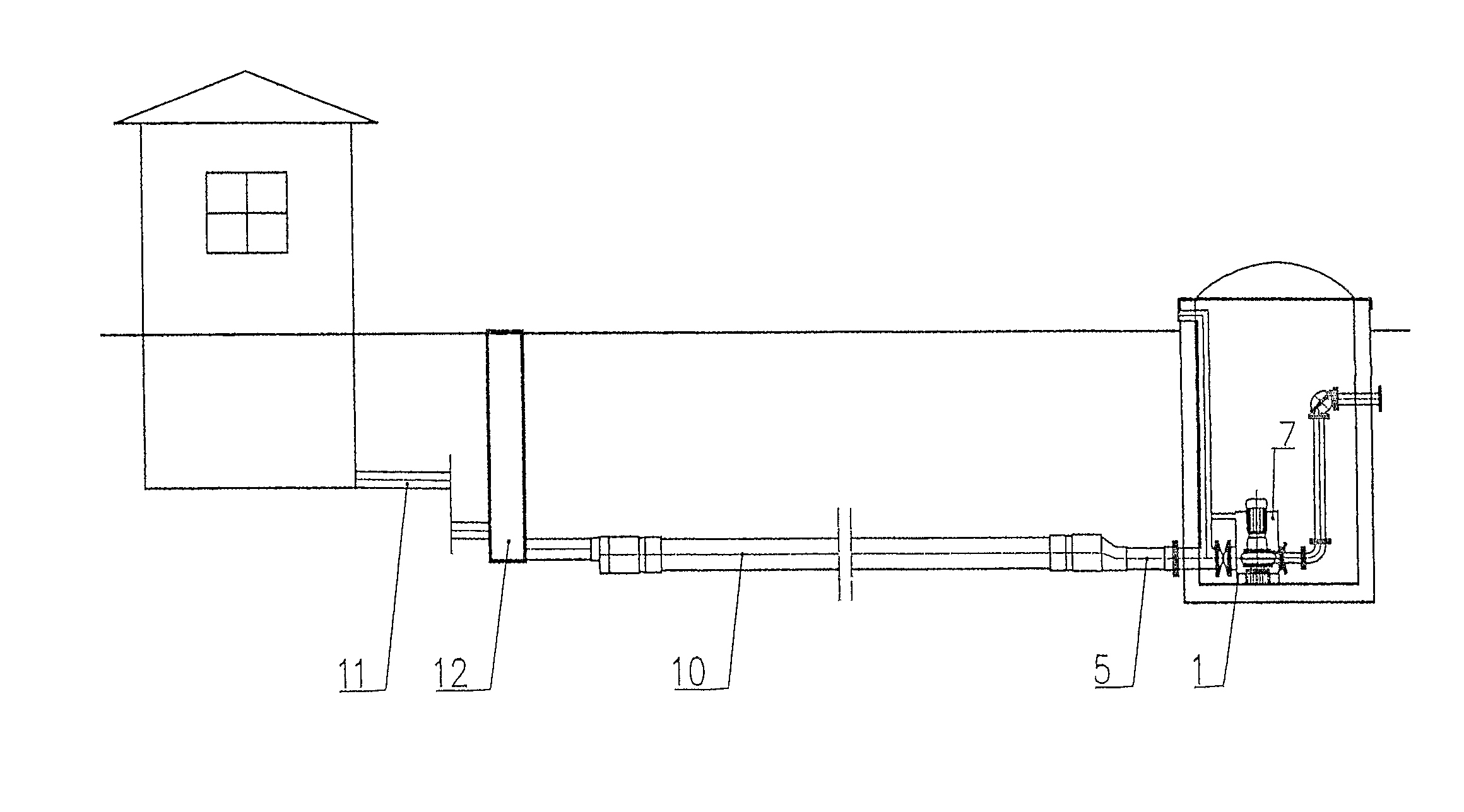
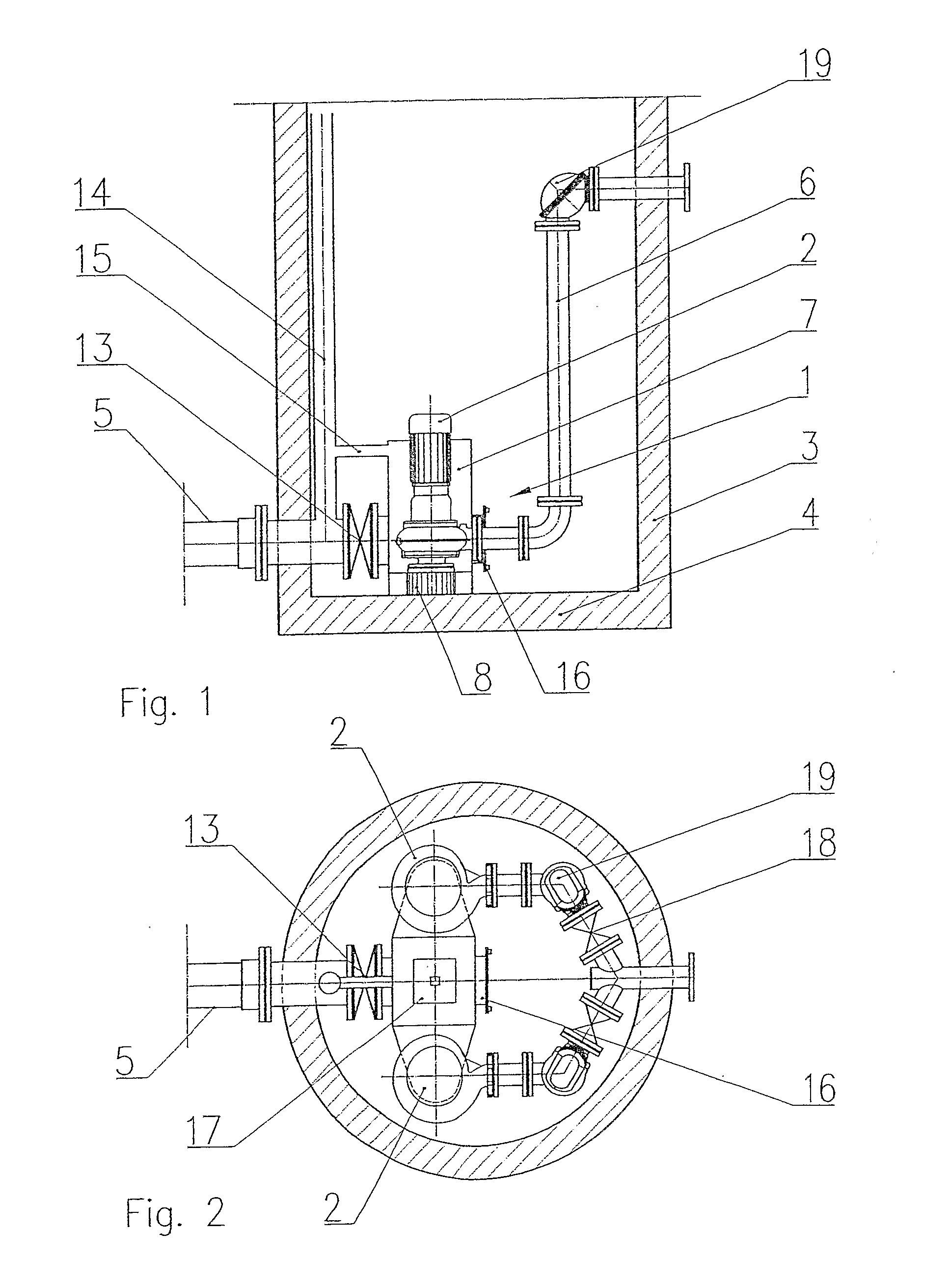
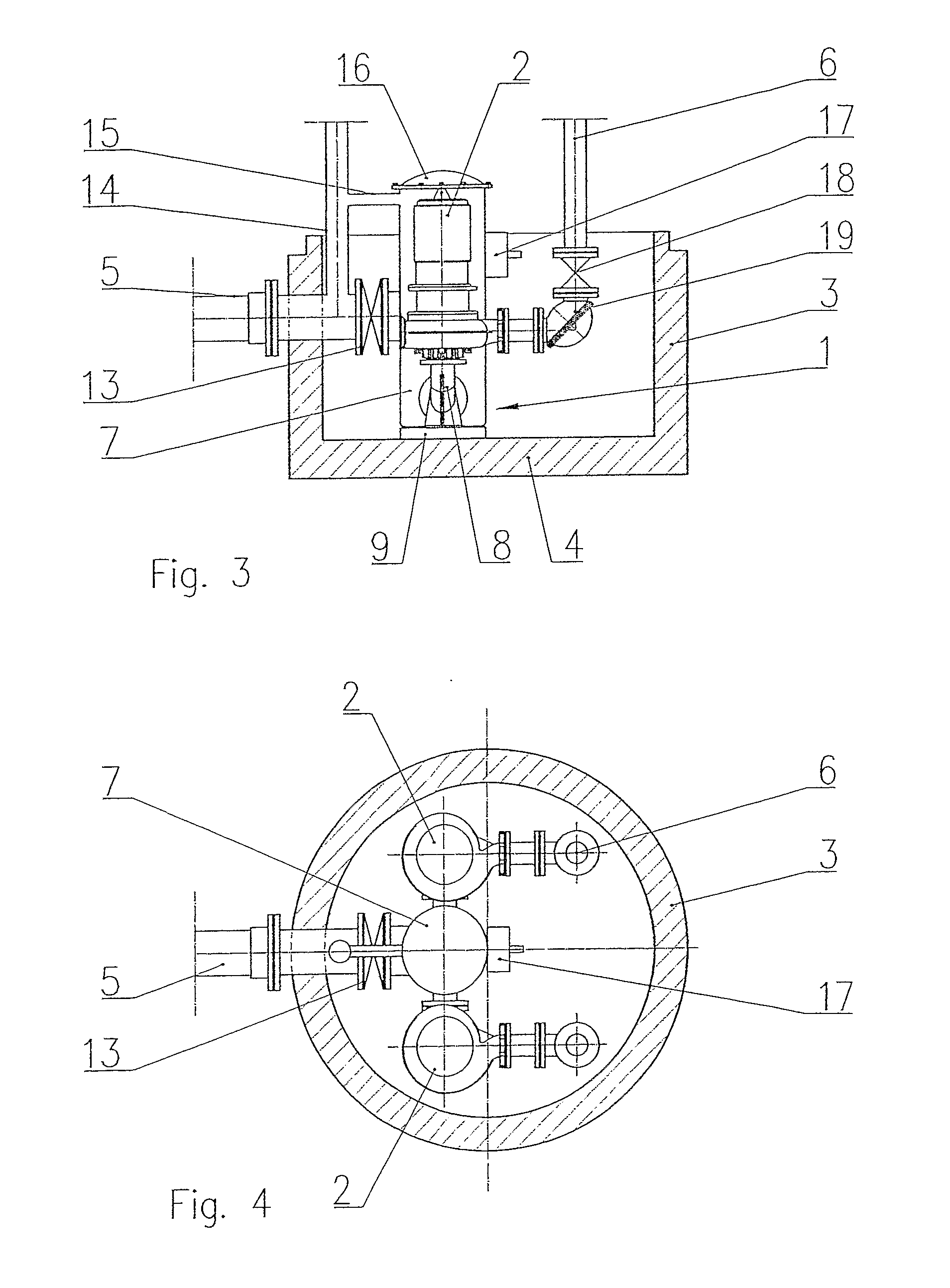
[0026]In the device according to the invention, the retention tank constitutes a distributing chamber which is connected to the external retention tank being a segment of a gravity-flow channel with its cross-section greater than the cross-section of gravity waste water transfer required in the calculations, located on the line of waste water inflow to the retention tank, whereas the capacity of the retention tank is at least two times smaller than the capacity of the external retention tank constituting a segment of the of the gravity-flow channel with its cross-section greater than the required cross-section of the gravity-flow channel for gravity waste water transfer required in the calculations.

[0027]The capacity of the retention tank is to the best advantage three to fifteen times smaller than the capacity of the external retention tank.

[0028]The operational capacity of the retention tank is to the best advantage four to twenty times smaller than the capacity of the external re...


PUM

PropertyMeasurementUnit
Pressureaaaaaaaaaa
Gravityaaaaaaaaaa

Abstract

In the device, according to the invention, the retention tank (7) constitutes a distributing chamber which is connected to the external retention tank (10) being a segment of a gravity-flow channel (11) with its cross-section greater than the cross-section of gravity waste water transfer required in the calculations, located on the line of waste water inflow to the retention tank (7), whereas the capacity of the retention tank (7) is at least two times smaller than the capacity of the external retention tank (10) constituting a segment of the gravity-flow channel (11) with its cross-section greater than the required cross-section of the gravity-flow channel (11) for gravity waste water transfer required in the calculations.

Description

[0001]This application is a '371 national stage entry of PCT International Application No. PCT / PL2007 / 000014, filed Mar. 22, 2007, claiming priority of Polish Applications Nos. P-382032, filed Mar. 22, 2007, and P-379265, filed Mar. 22, 2006, the entire contents of each of which are hereby incorporated by reference.FIELD OF THE INVENTION[0002]The invented object, a waste water pumping device, dedicated mainly for fecal waste water pumping installations. Besides, it can be applied in other pumping systems and its solutions can be used for modernization of the already existing waste water tank pumping stations.BACKGROUND OF THE INVENTION[0003]The classical waste water tank pumping stations employing immersed sewage pumps fixed automatically on a coupling footings immersed in the waste water pumped by them. The pumping station tanks in the developed versions have most commonly beds in a form of cone or sphere, which improves to some extent the hygienic conditions in the pumping station...

Claims


Application Information

Patent Timeline
IPC IPC(8): B01D47/00B65D88/64E03B5/00
CPCE03F5/22F04D15/0218F04F1/06Y10T137/86035Y10T137/86196
Inventor SZUSTER, MIROSLAWWOJCIECHOWSKI, RAFAL
Owner SZUSTER MIROSLAW
Why Eureka
Try Eureka