Container coupling device

a technology of coupling device and container, which is applied in the direction of loading/unloading vehicle arrangment, transportation items, load accommodation, etc., can solve the problems of difficult operation of the operation knob by the operator, high labor intensity, and high labor intensity, and achieves the effect of increasing the load efficiency of containers and simple structur

Active Publication Date: 2013-01-08
SANWA
View PDF14 Cites 15 Cited by
  • Summary
  • Abstract
  • Description
  • Claims
  • Application Information

AI Technical Summary

Benefits of technology

[0051]According to the present invention, even though the structure is very simple, a container to be loaded can be automatically and reliably coupled to a lower container simply by placing the container to be loaded on top of the lower container. Moreover, the coupled upper container can be automatically and reliably released from the lower container simply by lifting the upper container, so that the need for operation of a tool and high-place work is eliminated, and also there is no need for a complicated crane operation. Accordingly, loading and unloading of containers can be performed in a short period of time, and the gap between two containers that are adjacent in the front-and-rear direction and the lateral direction can be minimized, and therefore, the load efficiency of containers can be increased.

Problems solved by technology

In this case, it is difficult for the operator to reliably operate the operation knob 108 with the tip of the long tool, and therefore, there are problems in that much time is needed for the work and that operating the heavy, long tool causes intense fatigue.
Moreover, when the operator performs the operation from on top of the uppermost container Ct, the operator works at a high place, which entails danger such as accidentally falling down, and so there also is a drawback in terms of safety.

Method used


Image

  • Container coupling device
  • Container coupling device
  • Container coupling device

Examples


first embodiment

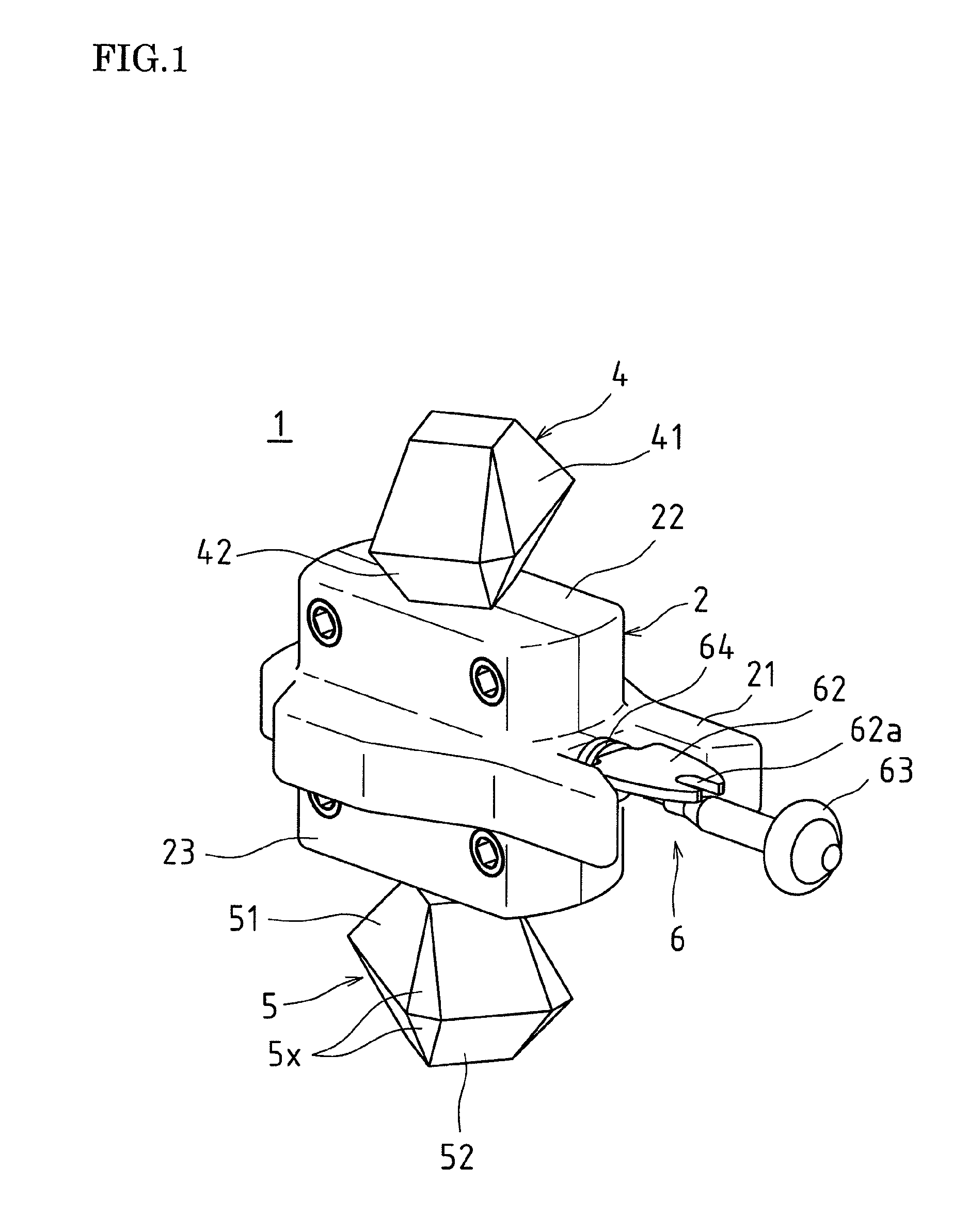
[0091]FIGS. 1 to 4 show a container coupling device according to a first embodiment of the present invention.

[0092]A container coupling device 1 includes, as its main parts, a device main body 2, a shaft 3, an upper fitting 4, a lower fitting 5, and an operating member 6, for example. The device main body 2 can be divided into two parts, and the two parts are fastened to each other into a single unit by a bolt. The shaft 3 is axially supported in the device main body 2 in a rotatable manner. The upper fitting 4 and the lower fitting 5 are integrally connected to an upper end and a lower end, respectively, of the shaft 3. The operating member 6 rotates the shaft 3, the upper fitting 4, and the lower fitting 5.

[0093]The device main body 2 has a main body portion 21 that is larger than an engaging hole Fa (see FIG. 20(b)) of a corner fitting F of a container Ct. Moreover, the device main body 2 includes an upper fitted portion 22 and a lower fitted portion 23 that are integrally formed...

second embodiment

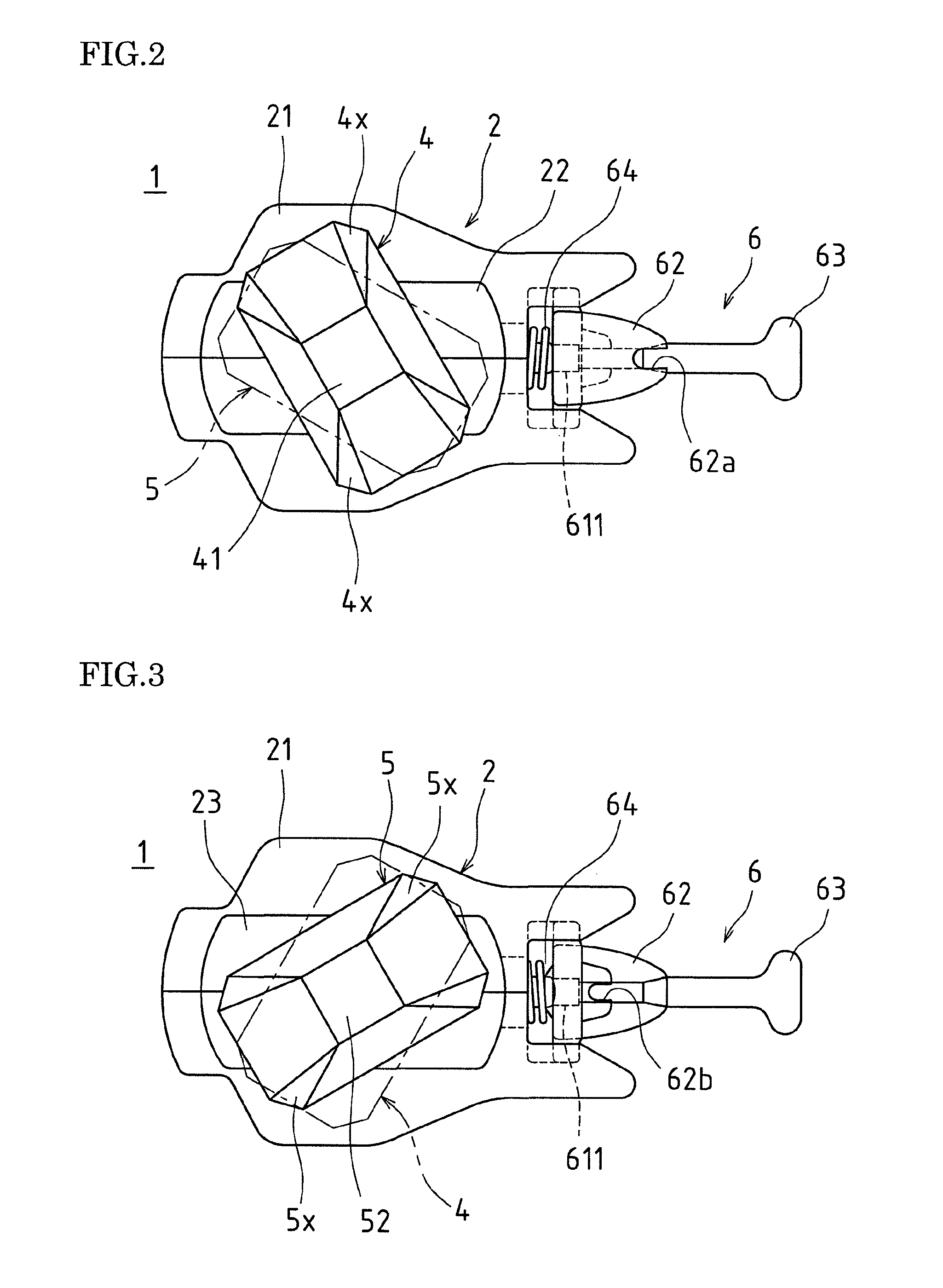
[0119]Next, a container coupling device according to a second embodiment of the present invention will be described.

[0120]It should be noted that in the following description of the container coupling device 1 according to the second embodiment, the same components as the components of the container coupling device of the above-described first embodiment are denoted by the same reference numerals, omitting their detailed descriptions, and differences from the first embodiment will be described in particular.

[0121]In the container coupling device 1 according to this embodiment, as shown in FIGS. 12 and 13, the device main body 2 can be divided into right and left parts, and the right and left parts are fastened to each other into a single unit by a bolt. The shaft 3 is axially supported in this device main body 2 in a rotatable manner, and the upper fitting 4 and the lower fitting 5 are integrally connected to the upper end and the lower end, respectively, of this shaft 3.

[0122]The d...


PUM


Abstract

According to a container coupling device 1 of an embodiment, when a container has been lifted with an upper fitting (4) and a lower fitting (5) being engaged with corner fittings (F) of an upper container and a lower container, respectively, via a spring mechanism, a container weight acts on a lower half portion (42) of the upper fitting (4) that crosses an engaging hole (Fa) of the corner fitting (F) of the upper container and on an upper half portion (51) of the lower fitting (5) that crosses an engaging hole (Fa) of the corner fitting (F) of the lower container. The upper fitting (4) and the lower fitting (5) are forcibly rotated against a biasing force of the spring mechanism in a direction in which the upper fitting and the lower fitting overlap an upper fitted portion (22) and a lower fitted portion (23), respectively. As a result, the lower fitting (5) rotates to a position at which the lower fitting overlaps the lower fitted portion (23) while the upper fitting (4) is engaged with the bottom corner fitting (F) of the upper container, and is thus released from the corner fitting (F).

Description

TECHNICAL FIELD[0001]The present invention relates to a container coupling device that can be disposed between vertically adjacent containers stacked in multiple levels in a container yard or on an container ship and used to couple the two containers together.BACKGROUND ART[0002]As shown in FIG. 15, loading and unloading of containers Ct between container yards Yd and container ships Sh have conventionally been performed.[0003]For example, in the case where a container Ct in a container yard Yd is loaded onto a container ship Sh, the container Ct is transferred from the container yard Yd onto a container conveying vehicle V such as a trailer by means of a transfer crane Tc or the like and then transported to an apron Ap. On the apron Ap, the container Ct is lifted by a spreader Sp of a container crane Cr and placed on top of another container Ct on a deck of the container ship Sb.[0004]On the other hand, in the case of unloading a container Ct from the deck of the container ship Sh,...

Claims


Application Information

Patent Timeline
Patent Type & Authority Patents(United States)
IPC IPC(8): B60P7/08
CPCB65D90/0013B65D2590/0033
Inventor FUKUI, FUMIMOCHI
Owner SANWA
Why Eureka
Try Eureka