

Pole part of a medium-voltage or high-voltage switch gear assembly, and method for its production
a technology of high-voltage switch gear and medium-voltage switch, which is applied in the direction of contact mechanism, high-tension/heavy-dress switch, air-break switch, etc., can solve the problem of significant thermal energy production
- Summary
- Abstract
- Description
- Claims
- Application Information
AI Technical Summary
Benefits of technology
Problems solved by technology
Method used
Image

Examples
Embodiment Construction
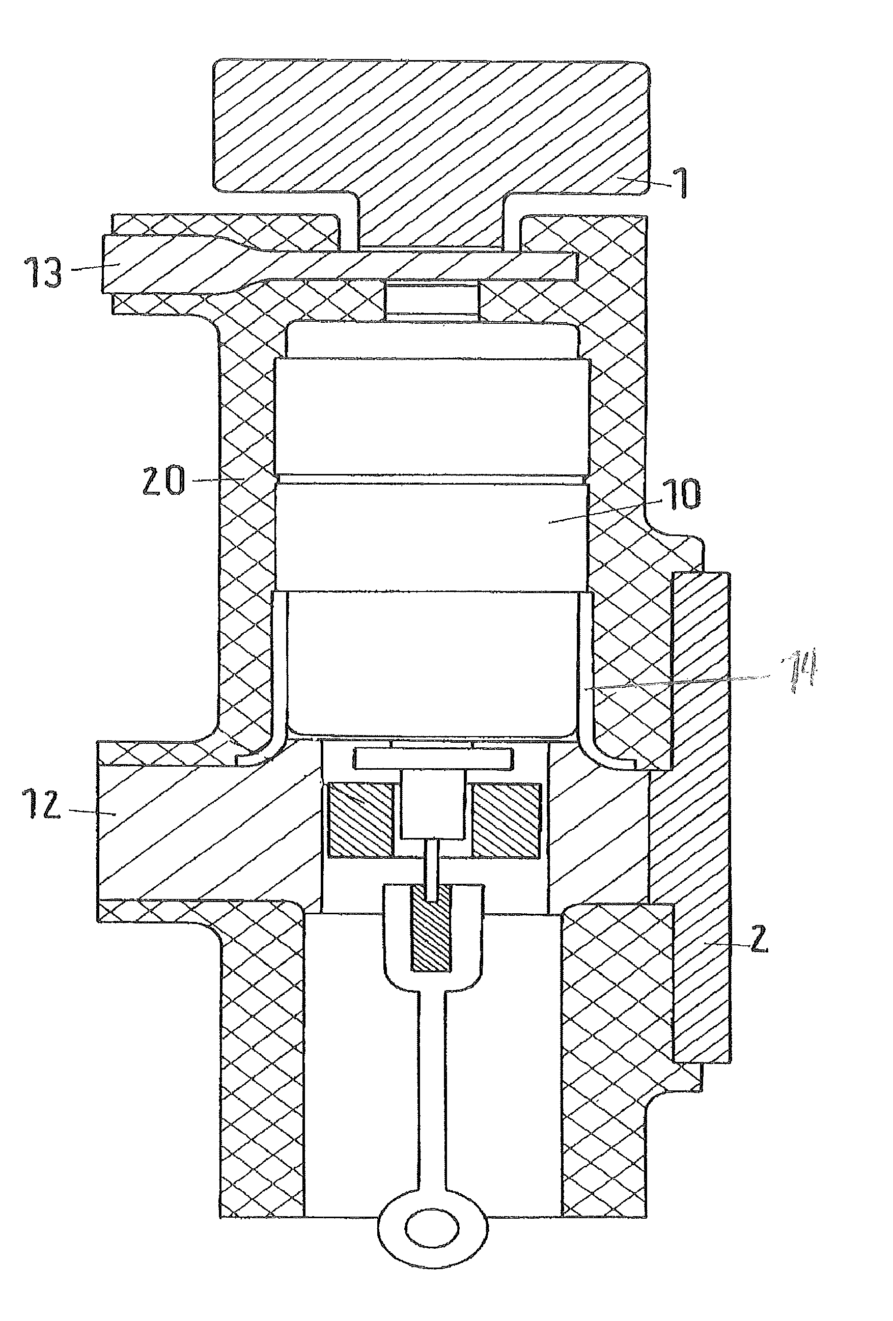
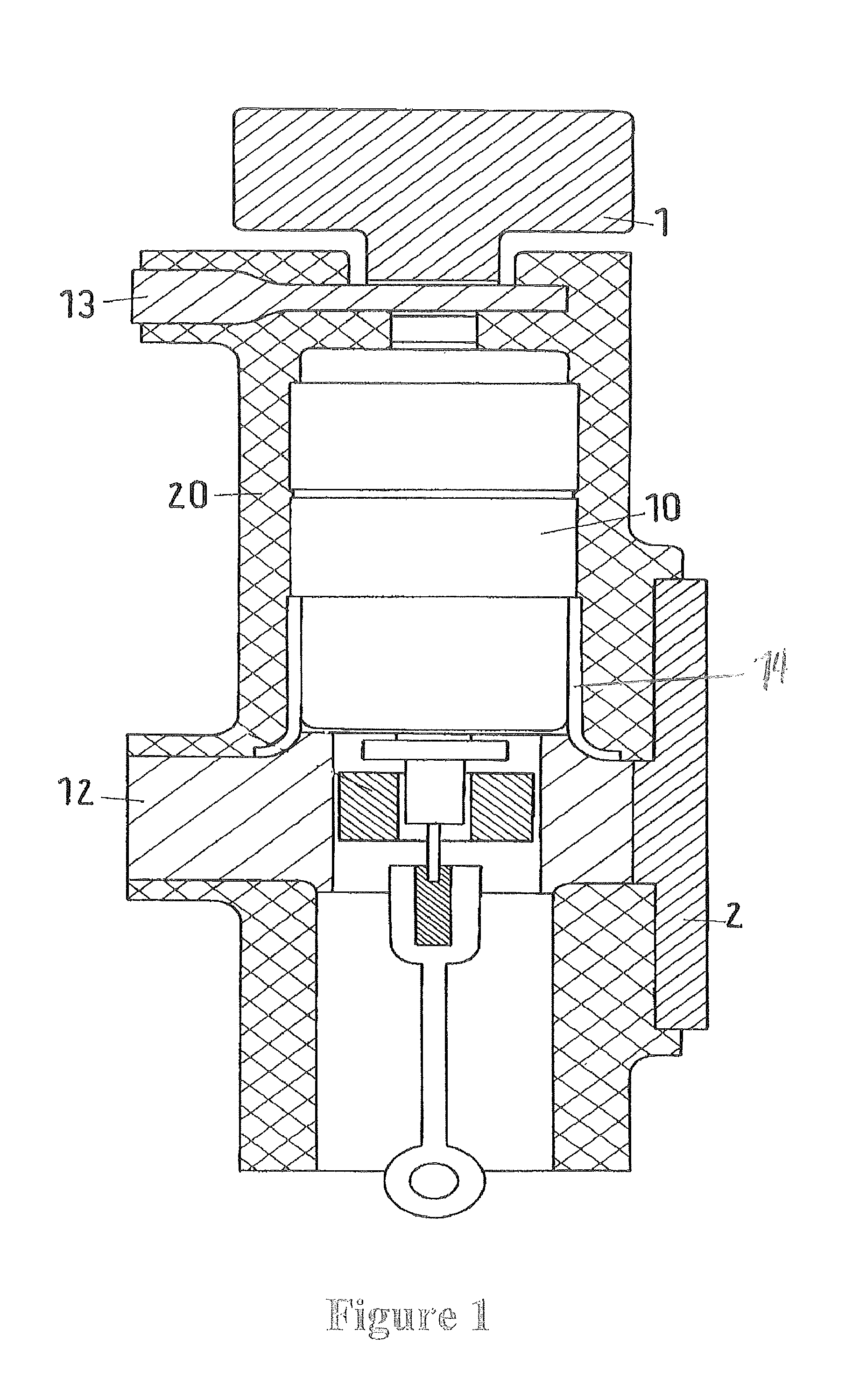
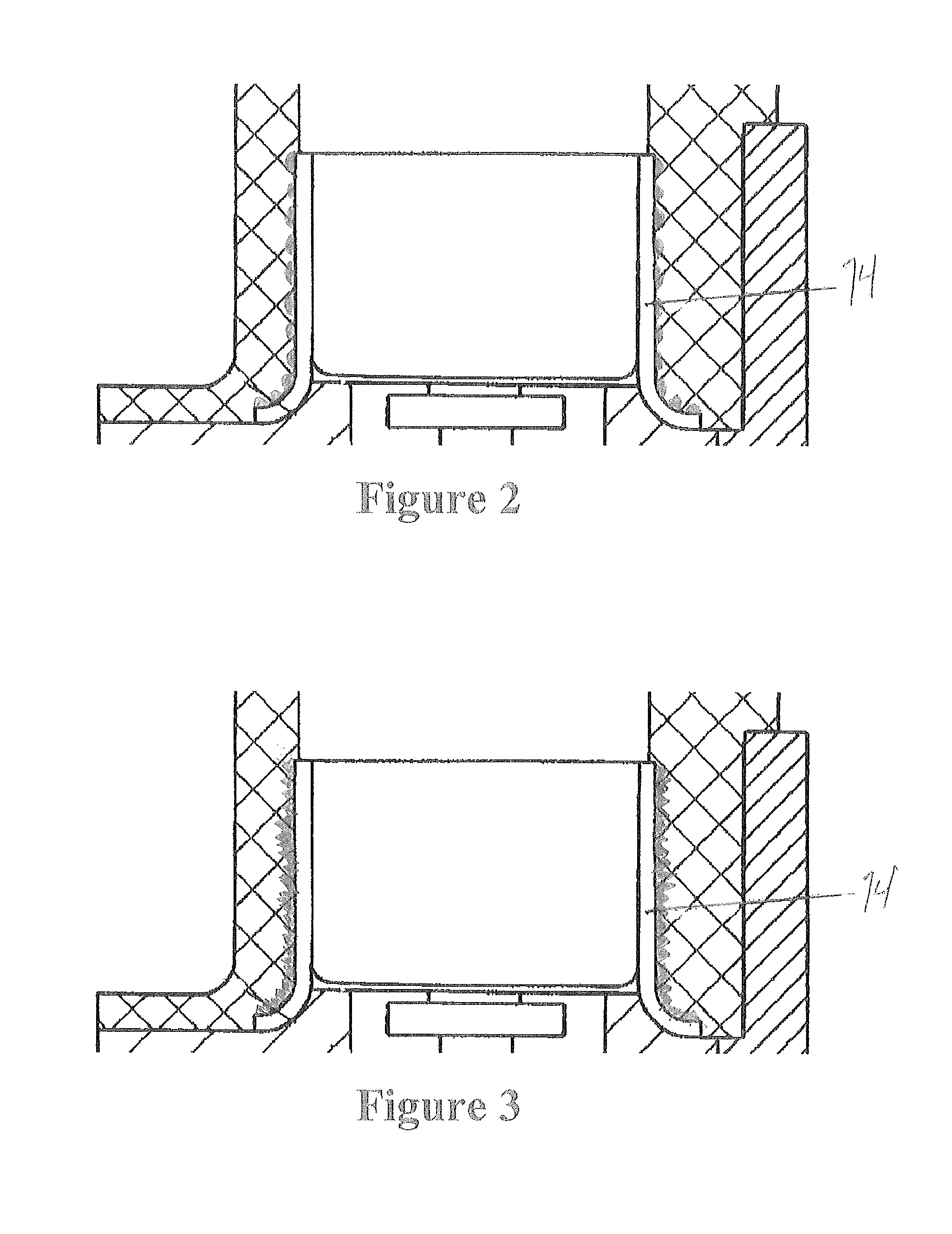
[0013]Exemplary embodiments of the present disclosure provide an improved pole part, and a method for producing such a pole part, such that heat that is created is dissipated better to the outside for convection.
[0014]In accordance with an exemplary embodiment, an electrically insulating or else conductive (and in consequence thermally conductive) heat transmission element, which is in the form of a cylindrical casing, is provided between the vacuum interrupter chamber and the encapsulation casing. An inner surface of the heat transmission element rests on a contact holder which passes on the thermal flow from here so that, with its outer surface, the thermal conduction on the encapsulation casing inner surface can be transmitted over a large area to the insulation material. According to an exemplary embodiment, the contact holder dissipates the heat flow from one of the two supply lines of a vacuum interrupter chamber outwards, passes the rated current via the connections to the ou...
PUM
| Property | Measurement | Unit |
|---|---|---|
| thermally conductive | aaaaa | aaaaa |
| length | aaaaa | aaaaa |
| thermal conductivity | aaaaa | aaaaa |
Abstract
Description
Claims
Application Information