Dynamic dimming LED backlight

a backlight and led technology, applied in the field of led backlights, can solve problems such as energy consumption becoming an issue, and achieve the effects of reducing power consumption, reducing power consumption, and prolonging product li

Active Publication Date: 2013-01-08
MFG RESOURCES INT INC
View PDF8 Cites 19 Cited by
  • Summary
  • Abstract
  • Description
  • Claims
  • Application Information

AI Technical Summary

Benefits of technology

[0007]Exemplary embodiments provide a backlight with individually controlled subsections. The luminance for each subsection can be controlled based on the image data being sent to the LCD. The incoming image data may be analyzed to determine the requirements for each subsection, and some may be selectively ‘dimmed’ if they correspond to portions of the image which do not require the full luminance output of the backlight. Selectively dimming portions of the backlight allows for several benefits, including but not limited to reduced power consumption, longer product lifetime, and higher contrast ratios.

Problems solved by technology

When used for extended periods of time and / or outdoors, overall energy consumption can become an issue.

Method used


Image

  • Dynamic dimming LED backlight
  • Dynamic dimming LED backlight
  • Dynamic dimming LED backlight

Examples


Embodiment Construction

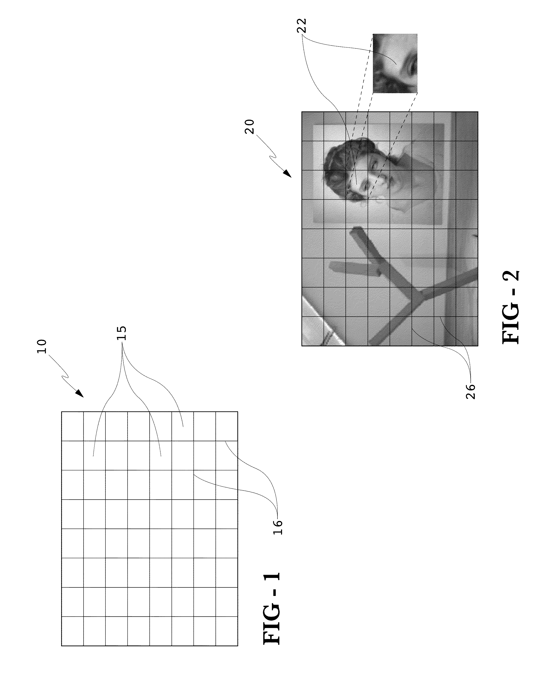
[0023]FIG. 1 shows a backlight 10 which has been divided into several individually-controllable subsections 15. The backlight 10 produces light through a plurality of LEDs (not shown) which are mounted to the front face of the backlight 10. In this example, an 8×8 array of subsections 15 is shown. However, any number, shape, and size of subsections may be used with the various embodiments. The number of actual subsections may depend upon: the size of the display, cost, complexity of controlling circuitry desired, and desire for maximum power savings. Ideally, the greater number of subsections will provide a higher level of control and performance by the system. It should be noted that lines 16 are only used to represent the divisions regarding control of the subsections 15 and are not required as actual lines or physical divisions of the backlight 10.

[0024]FIG. 2 provides the LCD image data 20, where this image is divided into subimages 22 which correspond with the subsections 15 of...


PUM


Abstract

A system and method for controlling subsections of an LED backlight for a liquid crystal display (LCD). Exemplary embodiments analyze the histograms for each subsection of the LCD which corresponds with the subsections of the LED backlight in order to produce a proper luminance for the backlight subsection. The proper luminance may be less than the maximum or typical luminance that is produced by common LED backlights. By reducing the luminance the resulting display can have less power consumption, longer lifetime, and higher contrast ratios. The original subpixel voltages for the LCD are re-scaled based on the proper luminance for the backlight subsection. Virtual backlight data may be created to simulate the luminance at each subpixel and the virtual backlight data may be used to re-scale the original subpixel voltages. The virtual backlight data may be used to blend between adjacent subsections of the LED backlight which may be producing different levels of luminance.

Description

CROSS-REFERENCE TO RELATED APPLICATIONS[0001]This application claims priority to U.S. Application No. 61 / 183,592 filed on Jun. 3, 2009, herein incorporated by reference in its entirety.TECHNICAL FIELD[0002]Disclosed embodiments relate generally to an LED backlight having individually controlled subsections and an associated liquid crystal display.BACKGROUND OF THE ART[0003]Liquid Crystal Displays (LCDs) contain several layers which work in combination to create a viewable image. A backlight is used to generate the rays of light that pass through what is commonly referred to as the LCD stack, which typically contains several layers that perform either basic or enhanced functions. The most fundamental layer within the LCD stack is the liquid crystal material, which may be actively configured in response to an applied voltage in order to pass or block a certain amount of light which is originating from the backlight. The layer of liquid crystal material is divided into many small regio...

Claims


Application Information

Patent Timeline
Patent Type & Authority Patents(United States)
IPC IPC(8): G09G3/36
CPCG09G3/3413G09G3/3406G02F1/133606G02F1/133603G09G3/36G09G3/3426G09G2360/12G09G2320/02G09G2320/0238G09G2320/0242G09G2320/0646G09G2320/066G09G2330/021G09G2360/16G09G2320/0233
Inventor WASINGER, JERRYDUNN, WILLIAM
Owner MFG RESOURCES INT INC
Why Eureka
Try Eureka