Head-mounted visual display device with stereo vision and its system

a visual display device and stereo vision technology, applied in the field of head-mounted visual display devices and systems, can solve the problems of not improving effectively the not making significant breakthroughs in color image processing, and not providing three-dimensional vision, so as to achieve effective clarity and brightness of video.

Inactive Publication Date: 2013-01-08
NATIONAL YANG MING UNIVERSITY
View PDF6 Cites 13 Cited by
  • Summary
  • Abstract
  • Description
  • Claims
  • Application Information

AI Technical Summary

Benefits of technology

[0026]a shifter (32) that receives the digital video signal captured by the cabled or wireless digital video extractor (31), processes left shift, left rotation, right shift and right rotation on the digital video signal and provides the two outputs of the digital video signal while the shift amount and the rotation angle can be set in advance by computer program or external controlling circuit setting via an interface;two color enhancement units (33) that simultaneously receive the two digital video signals bi-directional output provided by the shifter (32) and enhance the color contrast of the digital signals;two digital / analog (D / A) converters (34) that simultaneously receive the two color-contrast-enhanced digital video signal from the two color enhancement units (33) and convert to digital or analog according to the display unit;a head mounted display unit (35) that simultaneously receives the two video signals converted by the two D / A converters (34) and provides simultaneously the video of the two video signals;a signal voltage controller (36) with bi-directional electrical connection to the shifter (32) detects the voltage value, when a low-voltage is detected, a alerting signal is sent to the head mounted display unit (35).

Problems solved by technology

The current single-signal input HMD makes no significant breakthrough in color image process and can neither improve effectively the clarity and brightness of video nor provide three-dimension vision.

Method used


Image

  • Head-mounted visual display device with stereo vision and its system
  • Head-mounted visual display device with stereo vision and its system
  • Head-mounted visual display device with stereo vision and its system

Examples


Embodiment Construction

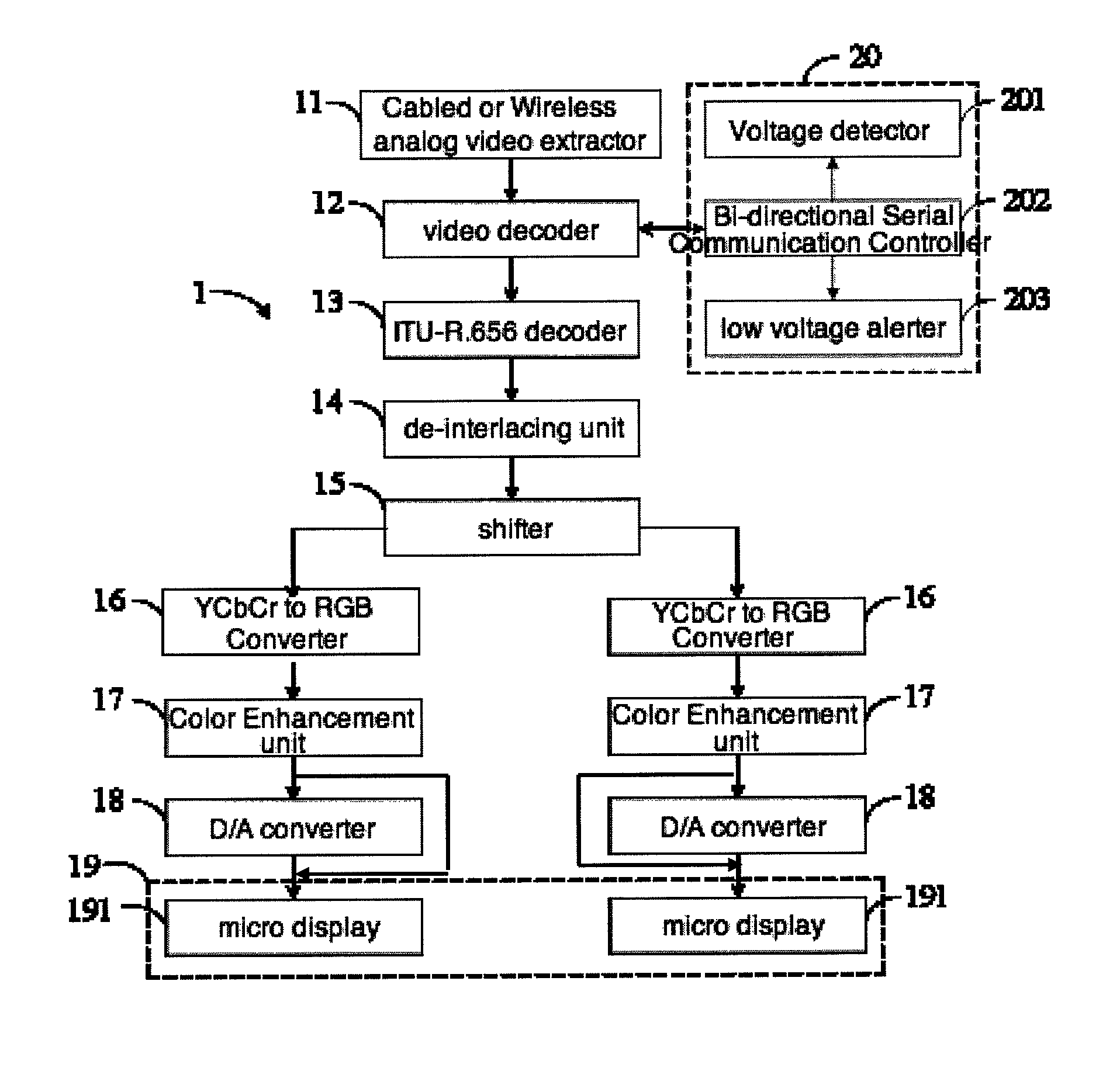
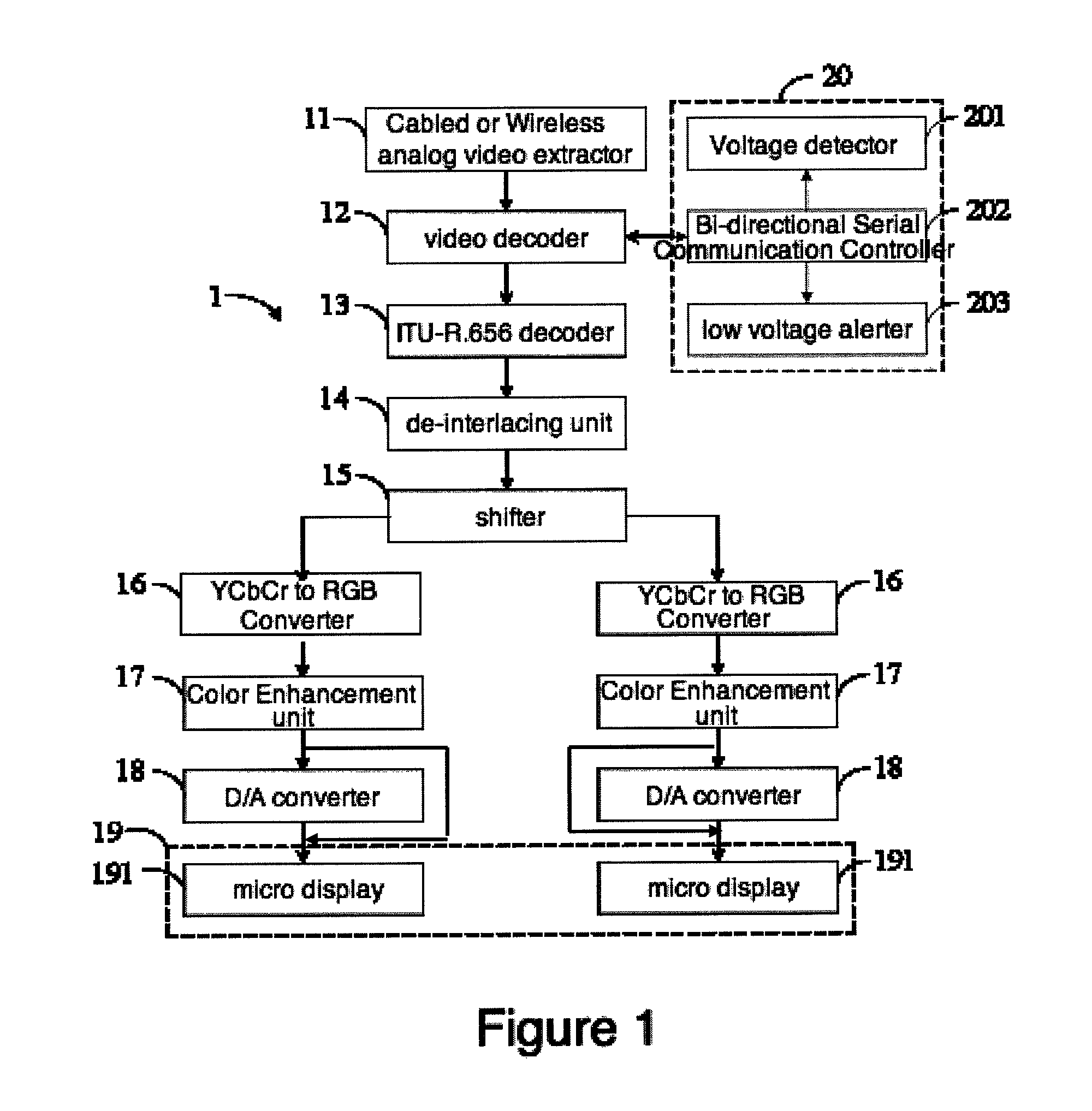
[0012]As shown in FIG. 1, the illustrative circuit diagram of the analog model of the present invention of a head mounted display device.

[0013]The analog signal model of head mounted visual display device (1) includes at least:

[0014]a cabled or wireless analog video extractor (11) that captures analog video signal of video data;

a video decoder (12) that receives the analog video signal from the cabled or wireless video extractor (11) and extract the analog video signal from the video;

a ITU-R.656 decoder (13) that receives the analog video signal extracted from the video decoder (12) and converts the analog video signal into digital video signal;

[0015]a de-interlacing unit (14) that receives the digital video signal converted by the ITU-R.656 decoder (13) and deinterlace the digital video signal that the signal will appear in sequence; a shifter (15) that receives the digital video signal processed by the de-interlacing unit (14), processes left shift, left rotation, right shift and ...


PUM


Abstract

A head-mounted visual display device for low-vision aid, which features 2 models, they are analog signal model and digital signal model. Said analog device contains at least an analog video extractor, a video decoder, an ITU-R.656 decoder, a de-interlacing unit, an image processor, two YCbCr to RGB converter, two color enhancement units, two video D / A converter, a head mounted display, a signal voltage controller and a wireless communication module. Said digital device consists of a digital video signal extractor / capturer, a RGB to YCbCr converter, an image processor, two YCbCr to RGB converter, two color enforcement units, a head-mounted display, a signal voltage controller and a wireless communication module.

Description

FIELD OF THE INVENTION[0001]The present invention generally relates to a head mounted visual display device and system and more particularly to a head mounted visual display device and system that processes separately the black and white elements and color elements of video signals to provide an optimal image quality in terms of clarity and brightness.BACKGROUND OF THE INVENTION[0002]The said head-mounted device (HMD) is a video display device that displays video provided by televisions, digital universal disc (DVD) devices, computer applications, game consoles or other similar appliances. The traditional single-signal input HMD can provide neither color contrast adjustment nor three-dimension vision and can easily lead to uncomfortable watching experience for users.[0003]The current single signal input HMD does not provide ideal color luminance and hence poor video clarity and the brightness. Therefore, how to improve the process of color luminance is one of the main tasks that the...

Claims


Application Information

Patent Timeline
Patent Type & Authority Patents(United States)
IPC IPC(8): H04N9/47H04N13/00H04N13/02H04N13/04
CPCG02B27/017H04N7/18H04N9/3182H04N9/646H04N9/68G02B2027/0138G02B2027/014G09G2340/06G09G2380/08
Inventor CHANG, YINLAI, YEN-LIUNGLI, JI-MINDU, YU-WEI
Owner NATIONAL YANG MING UNIVERSITY
Why Eureka
Try Eureka