System and method for providing gas turbine engine output torque sensor validation and sensor backup using a speed sensor

a technology of speed sensor and output torque sensor, which is applied in the field of gas turbine engines, can solve the problems of inaccurate torque sensor, inoperable other gas turbine engine components, and inability to properly control the gas turbine engin

Inactive Publication Date: 2013-01-08
HONEYWELL INT INC
View PDF49 Cites 170 Cited by
  • Summary
  • Abstract
  • Description
  • Claims
  • Application Information

AI Technical Summary

Problems solved by technology

Though unlikely, it is postulated that this torque sensor could become inaccurate, or otherwise inoperable, over time.
If this were to occur, the engine controller may not properly control the gas turbine engine and may lead technicians to believe that various other gas turbine engine components are inoperable.
This can lead to unnecessary and potentially costly engine down-times.

Method used


Image

  • System and method for providing gas turbine engine output torque sensor validation and sensor backup using a speed sensor
  • System and method for providing gas turbine engine output torque sensor validation and sensor backup using a speed sensor
  • System and method for providing gas turbine engine output torque sensor validation and sensor backup using a speed sensor

Examples


Embodiment Construction

[0015]The following detailed description is merely exemplary in nature and is not intended to limit the invention or the application and uses of the invention. Furthermore, there is no intention to be bound by any theory presented in the preceding background or the following detailed description. In this regard, although the invention is described in the context of a gas turbine engine, it could be implemented with other machines and in other environments.

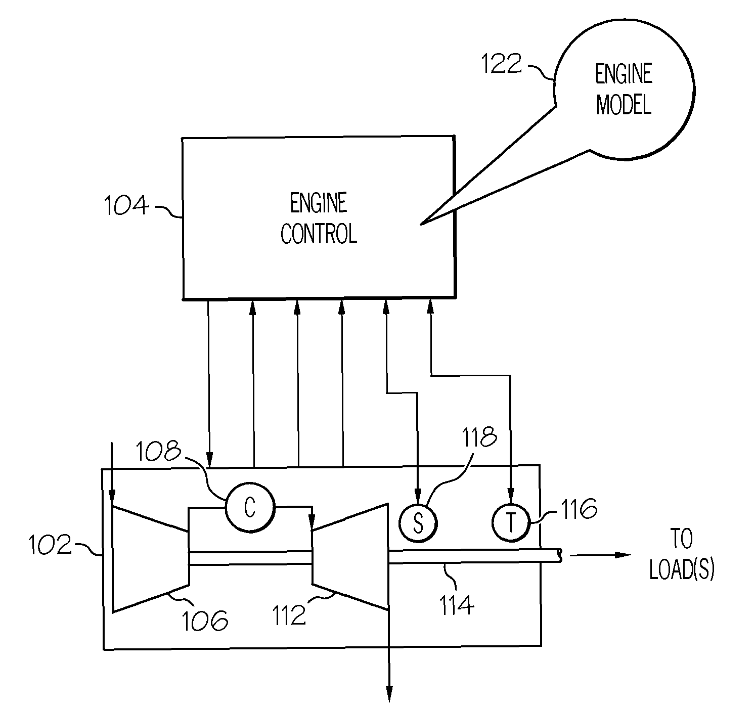
[0016]Referring now to FIG. 1, a functional block diagram of an exemplary gas turbine engine control system 100 is depicted. The system 100 includes a gas turbine engine 102 and an engine control 104. The depicted gas turbine engine includes a compressor 106, a combustor 108, and a turbine 112. The compressor 106 draws ambient air into the engine 102, compresses the air and thereby raises its pressure to a relatively high pressure, and directs the relatively high pressure air into the combustor 108. In the combustor 108, which incl...


PUM


Abstract

Methods and apparatus are provided for verifying proper operation of a gas turbine engine output torque sensor using a speed sensor, and using the speed sensor as a backup torque sensor. Gas turbine engine output torque is sensed using a reference torque sensor, and gas turbine engine output shaft rotational speed is sensed. Gas turbine engine output torque is calculated from the sensed gas turbine engine output shaft rotational speed. The sensed gas turbine engine output torque is compared to the calculated gas turbine engine output torque to determine if the reference torque sensor is operating properly. The gas turbine engine is controlled at least partially based on the sensed gas turbine engine output torque if the reference torque sensor is determined to be operating properly, and is controlled at least partially based on the calculated output torque if the reference torque sensor is determined to be not operating properly.

Description

TECHNICAL FIELD[0001]The present invention generally relates to gas turbine engines and, more particularly, to systems and methods for verifying the proper operation of a gas turbine engine output torque sensor using a speed sensor, and for using the speed sensor as a backup torque sensor.BACKGROUND[0002]Gas turbine engines may be used as the primary power source for various kinds of aircraft. The engines may also serve as auxiliary power sources that drive air compressors, hydraulic pumps, and industrial electrical power generators. Most gas turbine engines implement the same basic power generation scheme. That is, compressed air is mixed with fuel and burned to generate hot combustion gases. The expanding hot combustion gases are directed against stationary turbine vanes in the engine. The vanes turn the high velocity gas flow partially sideways to impinge onto turbine blades mounted on a rotatable turbine disk. The force of the impinging gas causes the turbine disk to spin at hig...

Claims


Application Information

Patent Timeline
Patent Type & Authority Patents(United States)
IPC IPC(8): G06F19/00G06G7/70
CPCF01D21/003F01D21/14F05D2270/304
Inventor MEACHAM, WALTER L.
Owner HONEYWELL INT INC
Why Eureka
Try Eureka