Supercharge Your Innovation With Domain-Expert AI Agents!

Hydraulic cylinder cushion

a hydraulic cylinder and cushion technology, applied in the field of spear-type hydraulic cylinder cushions, can solve the problems of reducing the effectiveness of spear-type cushions, i, axial alignment, and the rotation so as to increase the deceleration of the piston rod, prevent galling, and maintain constant clearance

Active Publication Date: 2013-01-15
HDM HYDRAULICS
View PDF10 Cites 2 Cited by
  • Summary
  • Abstract
  • Description
  • Claims
  • Application Information

AI Technical Summary

Benefits of technology

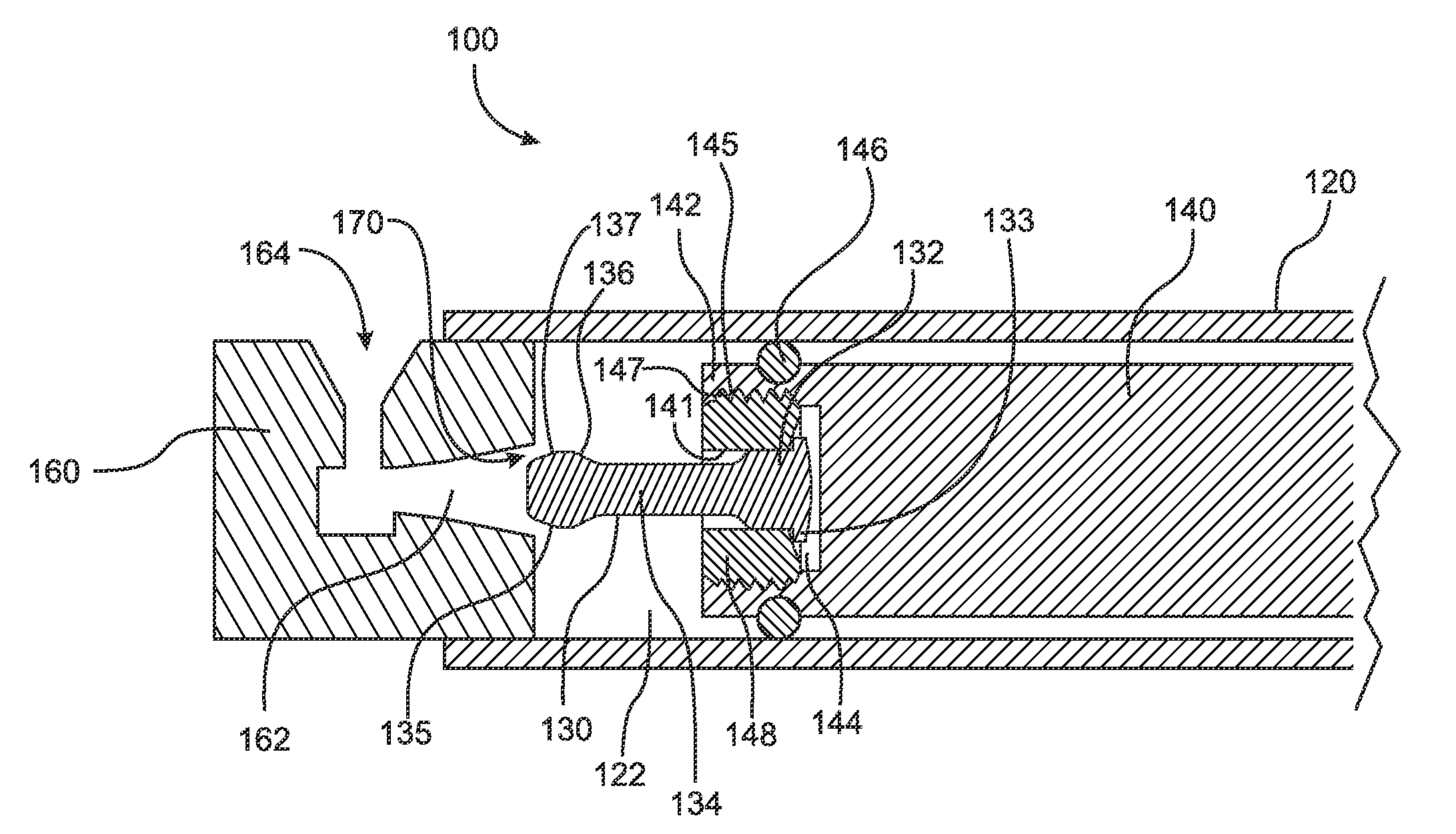
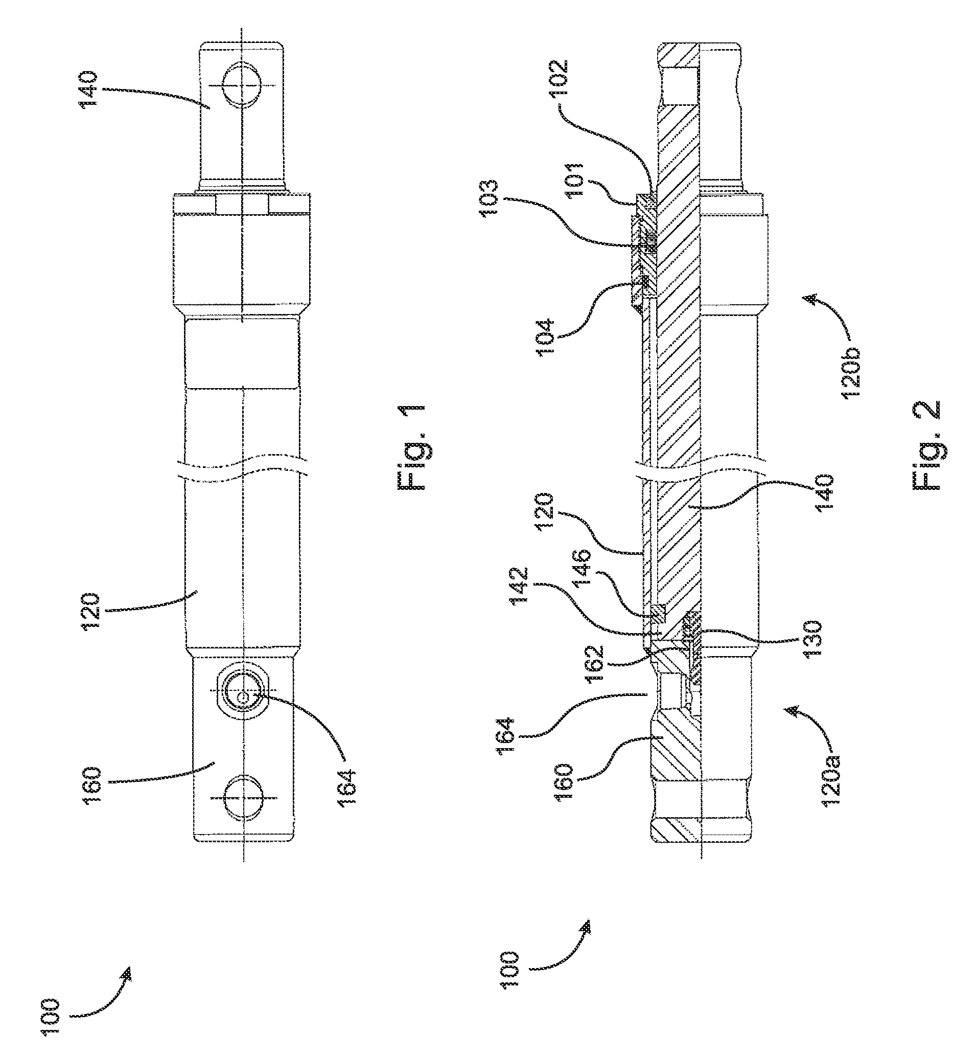
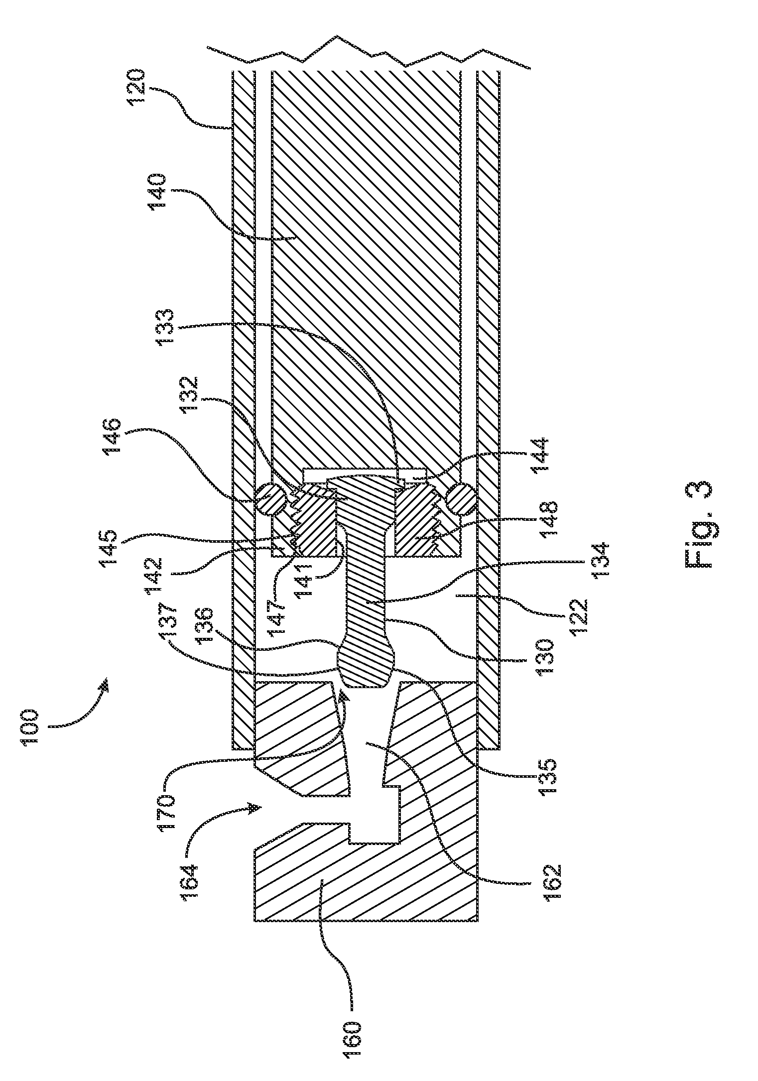
The present invention relates to a cushion spear apparatus that generates back pressure to decelerate the movement of a piston rod when the spear enters a bore. The spear is designed to pivot towards the longitudinal axis of the piston rod when the piston rod is radially shifted, and the spearhead and bore define an annular gap to create the back pressure. The piston rod includes a counter-bore and collar that allow for easy removal and replacement of the cushion spear, and the bore is tapered to create a progressive cushion effect. The spherical design of the tip of the spear provides a substantially constant clearance between the tip and the bore, regardless of the position of the spear. The spear and cushion may be made of different materials to prevent galling.

Problems solved by technology

However, many hydraulic cylinders, such as those utilized in snow plows, experience various loads which cause the piston rod to shift radially, i.e., out of axial alignment, within the cylinder.
Accordingly, the efficacy of spear-type cushions is reduced when this occurs, as the spear-like structure also becomes axially misaligned and cannot properly enter the bore in the end cap, which may also cause galling.

Method used


Image

  • Hydraulic cylinder cushion
  • Hydraulic cylinder cushion
  • Hydraulic cylinder cushion

Examples


Embodiment Construction

[0026]At the outset, it should be appreciated that like drawing numbers on different drawing views identify identical, or functionally similar, structural elements of the invention. While the present invention is described with respect to what is presently considered to be the preferred aspects, it is to be understood that the invention as claimed is not limited to the disclosed aspects.

[0027]Furthermore, it is understood that this invention is not limited to the particular methodology, materials and modifications described and as such may, of course, vary. It is also understood that the terminology used herein is for the purpose of describing particular aspects only, and is not intended to limit the scope of the present invention, which is limited only by the appended claims.

[0028]Unless defined otherwise, all technical and scientific terms used herein have the same meaning as commonly understood to one of ordinary skill in the art to which this invention belongs. Although any meth...


PUM


Abstract

A hydraulic cylinder cushion including a cylinder having a longitudinal axis and an inner chamber, a piston rod having a base, a cushion spear having a spear base, a shaft extending from the spear base, and a spearhead arranged opposite the spear base, the spearhead comprising a hemispherical portion connected to the shaft, wherein the hemispherical portion is diametrically larger than the shaft, and an end cap having a bore, wherein the end cap is secured to a first end of the cylinder such that the bore faces the inner chamber and is substantially aligned with the longitudinal axis, the piston rod is slidingly arranged within the inner chamber along the longitudinal axis such that the base faces the end cap, the cushion spear is pivotably secured to the base of the piston rod and extends toward the bore, and the bore is adapted to receive the cushion spear therein.

Description

CROSS-REFERENCE TO RELATED APPLICATIONS[0001]This application claims the benefit under 35 U.S.C. §119(e) of U.S. Provisional Application No. 61 / 200,263 filed on Nov. 26, 2008 which application is incorporated herein by reference in its entirety.FIELD OF THE INVENTION[0002]The invention broadly relates to hydraulic cylinder cushions and, more particularly, to spear-type hydraulic cylinder cushions.BACKGROUND OF THE INVENTION[0003]Spear-type hydraulic cylinder cushions are well known devices for decelerating piston rods and dampening their impact with end caps of hydraulic cylinders. Generally such cushions comprise a spear-like structure attached to the end of a piston rod and adapted to enter a bore in an end-cap. Upon entry into the bore, fluid restriction is increased, thereby decelerating the piston rod.[0004]However, many hydraulic cylinders, such as those utilized in snow plows, experience various loads which cause the piston rod to shift radially, i.e., out of axial alignment,...

Claims


Application Information

Patent Timeline
Patent Type & Authority Patents(United States)
IPC IPC(8): F15B15/22
CPCF15B15/226
Inventor MANNEY, III, CHARLES J.ANDERSON, WILLIAM J.STANCZYK, ERIC A.
Owner HDM HYDRAULICS
Features
  • R&D
  • Intellectual Property
  • Life Sciences
  • Materials
  • Tech Scout
  • Unparalleled Data Quality
  • Higher Quality Content
  • 60% Fewer Hallucinations
Learn More