Well bore control valve

a control valve and well bore technology, applied in the field of valves, can solve the problems of valves only cutting through a limited range of conduits, exposing limitations of devices, and unable to successfully remove fluids from pipes

Active Publication Date: 2013-01-15
ENOVATE SYST
View PDF13 Cites 37 Cited by
  • Summary
  • Abstract
  • Description
  • Claims
  • Application Information

AI Technical Summary

Benefits of technology

[0005]It is an object of the present invention to obviate or mitigate at least one of the aforementioned disadvantages.

Problems solved by technology

These devices have drawbacks however.
For example, sealing is generally achieved using elastomeric seals, the limitations of which are being exposed as more aggressive, high-temperature high-pressure, wells are developed.
Improved sealing can be achieved using valves to seal the throughbore, however currently available valves can only successfully cut through a limited range of conduits.

Method used


Image

  • Well bore control valve
  • Well bore control valve
  • Well bore control valve

Examples


Embodiment Construction

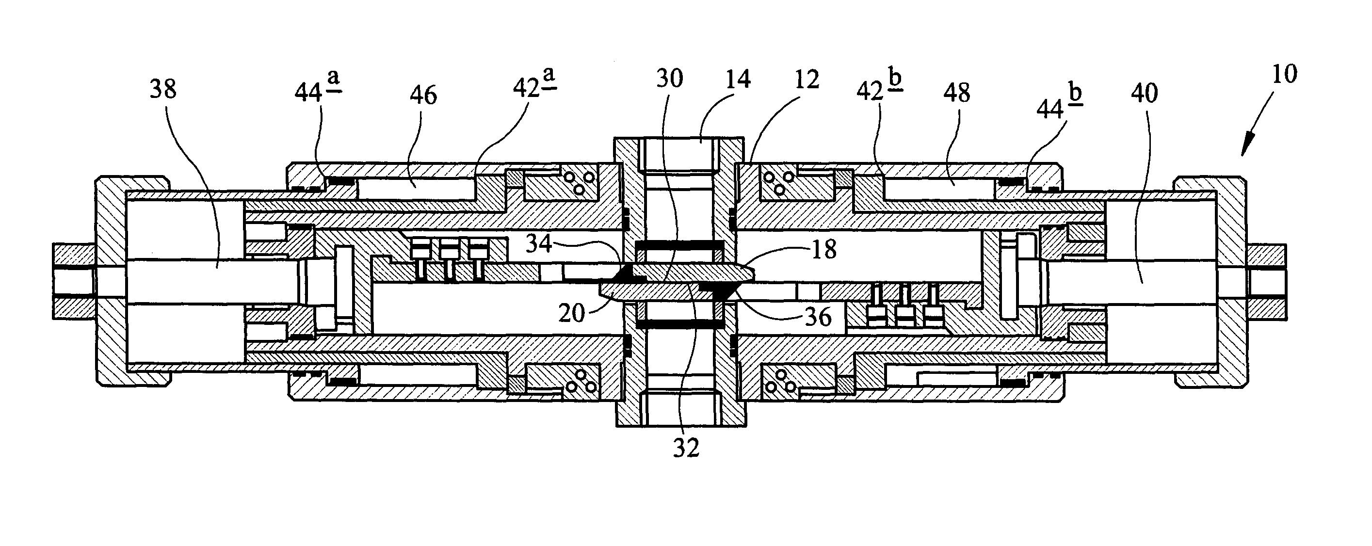
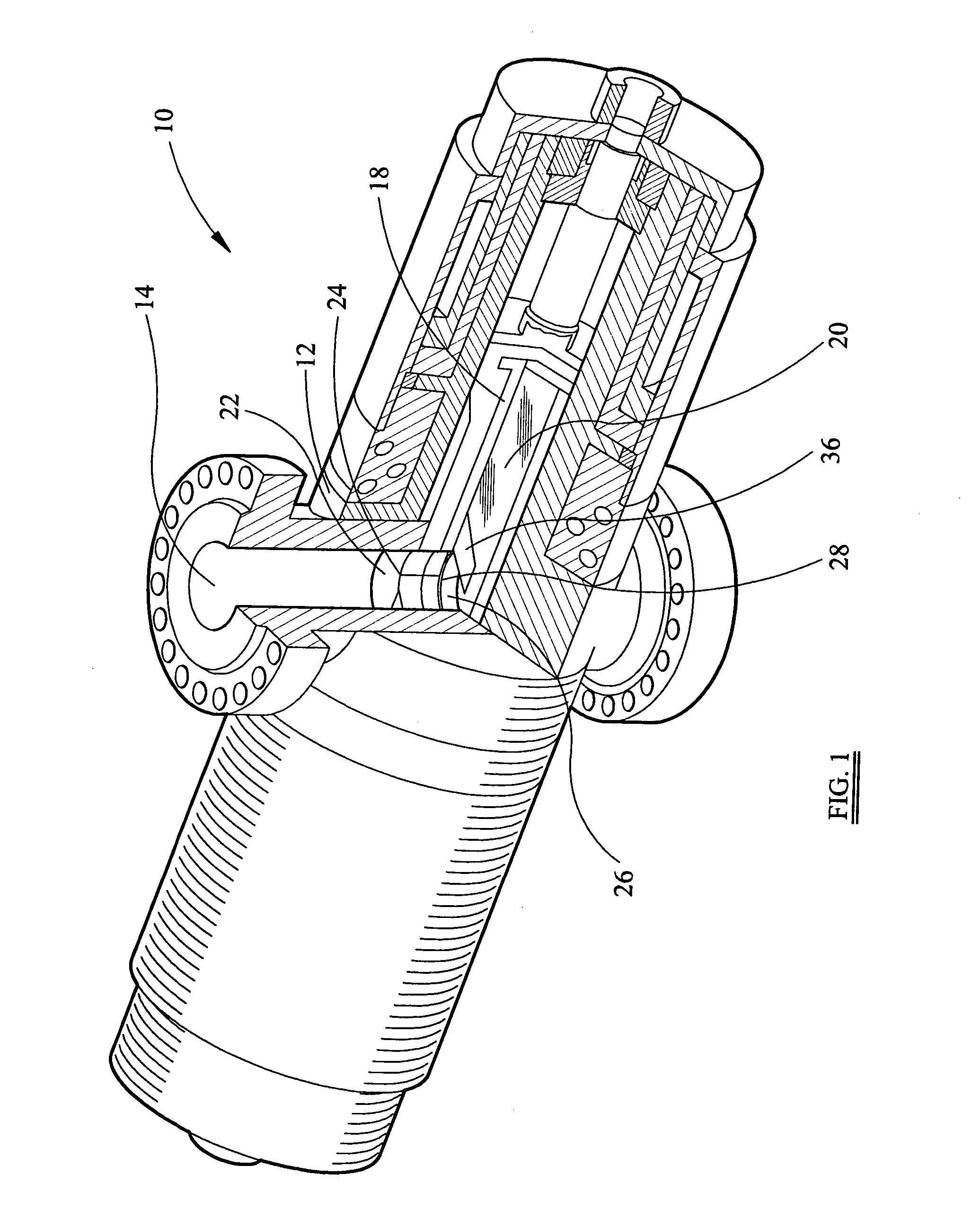
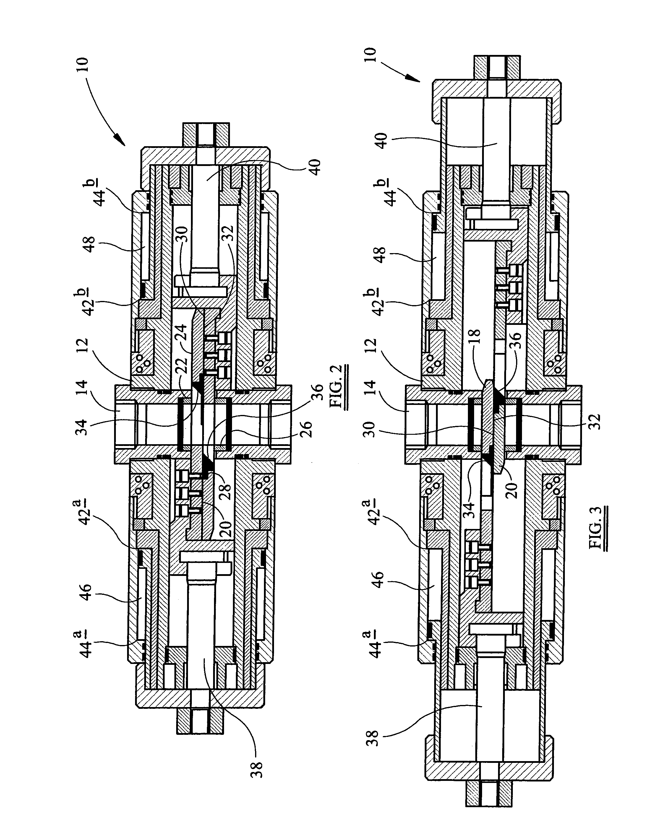
[0051]Referring firstly to FIG. 1, there is shown partially cutaway perspective view of a well bore control valve, generally indicated by reference numeral 10, according to an embodiment of the present invention shown in a throughbore open position, and FIG. 2, a longitudinal section view of the well bore control valve 10, also shown in the throughbore open position. The well bore control valve 10 comprises a housing 12 defining a throughbore 14, the throughbore 14 adapted to receive a workover conduit (not shown).

[0052]The well bore control valve 10 further comprises a first gate 18 and a second gate 20. The gates 18,20 are moveable between a throughbore open position, shown in FIGS. 1 and 2, and a throughbore closed position, shown in FIG. 3, a longitudinal section view of the well bore control valve 10 of FIG. 1 in the throughbore closed position. The gates 18,20 are made from corrosion resistant Inconel and are hard faced with tungsten carbide.

[0053]Referring particularly to FIG...


PUM


Abstract

The well bore control valve comprises a housing (12) defining a throughbore (14), the throughbore adapted to receive a first tubular. The valve further comprises first (18) and second gates (20) located within the housing, the gates being movable in different directions transverse to the throughbore between the throughbore open position and the throughbore closed position. Movement of the gates from the throughbore open position to the throughbore closed position, in use, shares a tubular located between the gates. The valve also comprises a first seal seat (22) performing a seal of one of the gates in the throughbore closed position to seal the throughbore. In one embodiment, the gates are axially movable with respect to the throughbore.

Description

FIELD OF THE INVENTION[0001]The present invention relates to a valve for sealing a throughbore, particularly but not exclusively for sealing a well bore through which a tubular, such as a workover / drilling conduit or intervention tooling passes.BACKGROUND OF THE INVENTION[0002]For the protection of personnel and the environment, oil installations are provided with one or more well bore control devices, such as a riser control device or a blow out preventer, for sealing the well bore.[0003]Some well bore control devices have cutting rams mounted perpendicular to a vertical throughbore. The rams can be activated to sever a tubular disposed in the wellbore and seal the well bore. The cutting rams move through a horizontal plane and are often driven by in-line pistons. These devices have drawbacks however. For example, sealing is generally achieved using elastomeric seals, the limitations of which are being exposed as more aggressive, high-temperature high-pressure, wells are developed....

Claims


Application Information

Patent Timeline
Patent Type & Authority Patents(United States)
IPC IPC(8): E21B33/06E21B29/00
CPCF16K3/029E21B33/063
Inventor EDWARDS, JEFFREY CHARLES
Owner ENOVATE SYST
Why Eureka
Try Eureka