Product storage and retrieval system

a product storage and product technology, applied in the field of product storage and retrieval system, can solve the problem that products cannot be placed in containers, and achieve the effect of easy identification and easy retrieval

Active Publication Date: 2013-01-15
MAXOR NAT PHARMACY SERVICES LLC
View PDF33 Cites 30 Cited by
  • Summary
  • Abstract
  • Description
  • Claims
  • Application Information

AI Technical Summary

Benefits of technology

[0006]One or more of a specific product is placed in the container. The product and the hanger address are associated with each other and recorded on a computer database that is networked to one or more client computers. The containers can be various different structures including: bags, boxes, envelopes, etc. In order to help identify the products within the container, the container may be made from a translucent or transparent material. The container may have a closure, cover, latch or other device which allows the contents of the bag to be accessed and prevents the goods from accidentally falling out of the container. In some situations, the products cannot be placed in the containers. Instead of storing the goods in the container, a place card indicating the location of the goods may be placed in the container so the user can locate the desired goods. For example, if the goods are too large to fit in the container, the place card may indicate the larger storage location for the goods. If the goods require refrigeration, the place card may indicate that the goods are being stored in a refrigerated storage area. If the goods are controlled substances, the place card may indicate that these goods are stored in a locked area and additional security measures may be required to access the goods. If the goods are special prescription drugs that require a pharmacist to fill the prescription only when the patient arrives, the place card may indicate these requirements and provide the prescription filling instructions. The place card can provide various other location and instructional information for the goods.
[0007]When a recipient wishes to pick up the ordered goods, identification information for the ordered goods is input into a client computer. The computer searches the database to determine the address of the hanger associated with the goods. Once the address is found, the client computer instructs a radio frequency transmitter to emit a data packet that includes the address associated with the goods and is transmitted to the storage area where the hangers are kept. All of the hangers in the storage area receive the packet and compare the address to the assigned hanger address. In one embodiment, the hanger having a matching address responds by illuminating an indicator light (possibly a multi-colored light emitting diode) built into the hanger. All other hangers that are not the correct address will not react to the address signal and will continue to monitor for new incoming address packets. The computer operator will be informed about the color light on the hanger associated with the matching address and then the operator can easily locate the corresponding illuminated hanger and provide the contents of the container to the recipient of the goods.
[0010]While the hanger is placed on the rail, the electrical contact provides power to the electrical components of the hanger. In the preferred embodiment, the electrical power is low voltage direct current which minimizes the possibility of electrocution. Thus, the electrical components may be damaged if the polarity of the pins and conductive strips is reversed. The rail may be designed so that it is impossible to reverse the polarity of the power by reversing the connections of the pins to the conductive strips. When the hanger is removed from the rail, the electrical components of the hanger are powered by a rechargeable power supply such as an in internal battery. The internal power supply allows the hanger to continue to operate by illuminating the lights when the radio frequency signal with the corresponding address is received. The power supply may provide enough power for the internal components to operate for one or more hours before recharging is required.
[0012]In other embodiments, the hangers may receive electrical power from the storage rails through an inductive charging mechanism rather than the direct contact conductive charging mechanism described above. The induction charging mechanism may use induction coils to create alternating electromagnetic fields from within the rail. Each of the hangers may include an induction coil that is placed in the hook portion of the hangers that takes power from the electromagnetic field and converts it back into electrical current to charge the internal rechargeable power supply. In order for the hangers to obtain power from the rail, the two induction coils must be in close proximity to each other. In order to align the coils, the rail may have many coils centered across the width and equally spaced along the length of the rail. In order to align the hangers with the coils, the rail may have alignment mechanisms such as a recessed portion that allows the hook portion of the hangers to be placed directly over the coils. The recessed area may correspond to the width of the hook portion of the hanger. Alternatively, the primary inductive coil in the rail can extend along the length of the rail. The charging coil of the hanger may be within the tab section and the hangers may be able to slide along the length of the rail while still allowing for inductive power transfer to the hanger. A benefit of inductive charging is that there are no exposed electrically conductive surfaces. The coils are preferably concealed within the housing of the hangers. This configuration minimizes the possibility of foreign objects preventing the conductive components from contacting each other.
[0017]While the invention has been described with reference to delivery of pharmaceuticals, the inventive system can be used for various different storage and distribution applications. The products can be stored by product type wherein each of the containers holds a single product. When a user needs several different products, a different hanger must be obtained for each product. The system can be configured to illuminate all of the hangers needed to fill an order with the same light color(s) and illumination pattern. This allows the user to locate and collect all hangers that are needed. When the quantity of product runs low, the product placed in the container can be replenished and the hanger replaced on the rack. Since the product remains the same for the hanger, the hanger can always be associated with the same product.
[0018]Alternatively, each container can store a group of different products that have been picked in order to fill an order for a recipient. This embodiment may be particularly suitable for pharmacies where patients require specific quantities of several different medications. In this embodiment, a patient may receive a prescription for several medications. The prescriptions can be forwarded to the pharmacist who gathers the prescribed drugs and places them in a single container coupled to a hanger. The hanger and coupled container are associated with the patient on the computer system and stored on a rack in the storage area. When the patient arrives at the pharmacy to pick up the prescription, the pharmacist can input identification for the patient and the computer will transmit the radio frequency signal to the hangers. The hanger coupled to the container holding the patient's medication will be illuminated and easily identified so the medication can be easily retrieved and given to the patient.

Problems solved by technology

In some situations, the products cannot be placed in the containers.

Method used


Image

  • Product storage and retrieval system
  • Product storage and retrieval system
  • Product storage and retrieval system

Examples


Embodiment Construction

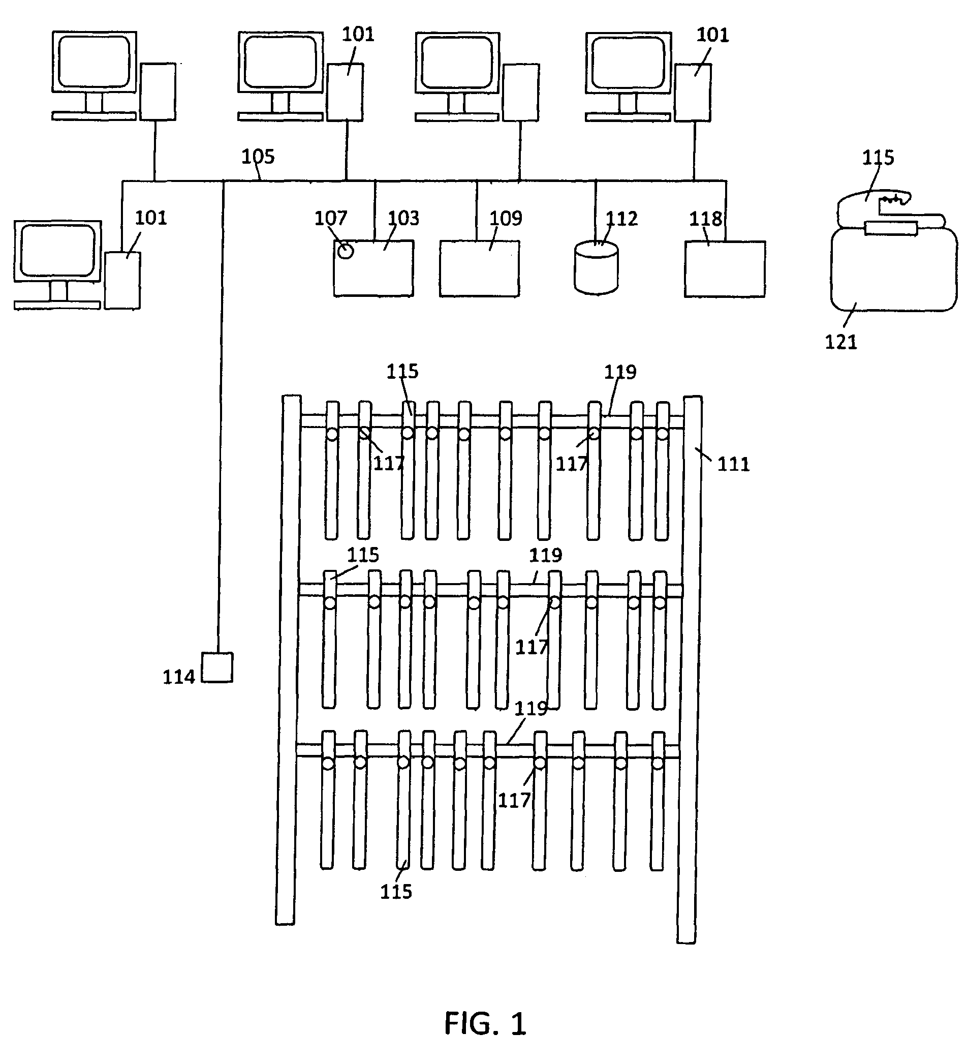
[0034]The present invention is directed towards an apparatus and system for storing and locating products within a storage area. With reference to FIG. 1, in an embodiment the inventive system includes several separate components. The inventive system can be used with a computer network having a plurality of client computers 101. The clients 101 are coupled to one or more radio frequency (RF) transmitters or transceivers 103. One or more of the clients 101 can be an administrative computer that controls the operation of the inventive system. The RF transmitters or transceivers 103 may be coupled to one or more status lights 107 which can indicate that the transceiver 103 is operating properly. For example, a green light may be illuminated when the transceiver 103 is connected to the network. A red light may indicate that the transceiver is powered and functional. The red light may blink when there is an error in the system. A yellow light may indicate that the wireless receiver is e...


PUM


Abstract

A system for easily locating goods stored in a storage area including a computer coupled with a radio frequency transmitter or transceivers and goods placed in containers that are coupled to hangers that each has distinct electronic addresses. The hangers each have a hook that allows the hangers to be stored on rails coupled to racks in a storage area. The identifications of the goods and the electronic addresses for the corresponding hangers are associated with each other and stored on a computer database. When a user wants to pick up goods stored in the containers, the user inputs the identification for the goods and the computer will cause the radio frequency transmitter to emit a data packet that includes a search address and illumination data. The hangers each compare the search address to the electronic address and if there is a match, the hanger illuminates the light according to the illumination data. The system notifies the user of the color and flash pattern and the goods can then be easily found by locating the hanger having the corresponding illumination.

Description

BACKGROUND[0001]An inventory of goods is frequently stored in a storage area. The distribution of the goods is monitored and controlled by an inventory worker. When an order is placed for the goods, a pick list is produced and the inventory worker obtains the required quantities of each of product on the pick list. The ordered goods can then be placed in a temporary storage area until the order is picked up. Because many orders can be placed at the same time, the filled orders must also be identified and organized so they can be easily located and given to the proper recipient. When the order is picked up, order information or identification information is given to the inventory worker who locates the filled order and gives the order to the recipient.[0002]When the goods are controlled, it may be necessary to store the goods in a secure area. For example, a pharmacy may store many different drugs in an area that is only accessible to authorized employees such as pharmacists. A presc...

Claims


Application Information

Patent Timeline
Patent Type & Authority Patents(United States)
IPC IPC(8): G06Q10/00
CPCG06Q10/087G06Q10/08G06Q50/22G16H20/10
Inventor DELANEY, KEVIN C.GUILLERMO, ROBERT G.LIM, KENDRICK S.PONFERRADA, ROY G.CRAS, WILLIAM S.LEE, RICHARD M.VICTORIA, DAVID A.
Owner MAXOR NAT PHARMACY SERVICES LLC
Why Eureka
Try Eureka