Ion mobility sensor system

a technology of mobility sensor and ion, which is applied in the field of ion mobility sensor system, can solve the problems of labor intensive sampling, large time consumption, and expensive laboratory analysis, and achieve the effects of improving resolution and contaminant identification, improving the monitoring of chlorinated hydrocarbons, and facilitating the movement of ions

Active Publication Date: 2013-01-22
UT BATTELLE LLC
View PDF15 Cites 45 Cited by
  • Summary
  • Abstract
  • Description
  • Claims
  • Application Information

AI Technical Summary

Benefits of technology

[0018]One or more aspects of the present invention provide the advantage of the versatility to use multiple filters with different permeable membranes to allow the permeation of numerous distinct molecules, thereby collecting a plurality of specific contaminants for analysis by the ion mobility sensor system.
[0019]One or more aspects of the present invention provide the advantage of providing improved monitoring of chlorinated hydrocarbons in groundwater due to improved resolution and contaminant identification.
[0020]One or more aspects of the present invention provides the advantage of being able to operate in ambient atmospheric pressure without the need of a vacuum and can be micro-fabricated in a compact size.
[0021]One or more aspects of the present invention provide the advantageous tandem combination of an IMS spectrometer first followed by a DMS spectrometer. This tandem combination may have an overlapping interface defined as the space between the second B-N gate in the IMS spectrometer and DMS spectrometer entrance electrode. The ion drivers in the IMS spectrometer and DMS spectrometer may be overlapped in the interface region, with the IMS spectrometer ion driver being an electric field and the DMS spectrometer ion driver being a flowing gas. This interface region may be configured so that within this region, an electric field and a gas flow operate jointly to help facilitate the movement of ions from the exit of the IMS spectrometer to the entrance of the DMS spectrometer. The electric field may be in the same direction as the drift field of the IMS spectrometer. The gas flow may be the same flow used to drive ions in the DMS filtration gap towards the second electrode of the DMS spectrometer. This IMS / DMS interface can ensure the transport of ions from the IMS spectrometer exit to the DMS spectrometer entrance without incurring a significant loss of ions.

Problems solved by technology

Long-term monitoring (LTM) of these pollutants is needed not only because of their potential hazard, but also due to the reality that complete cleanup of significant DNAPL source zones has not been, and most likely will not be, possible.
Most LTM approaches usually involve the installation and maintenance of monitoring wells, labor intensive sampling, and costly laboratory analysis.
These technologies are complex, large, time-consuming, require substantial utilities (power and vacuum), and have high associated costs.
This “flow-over,” however, is difficult to implement due to conflicting requirements related to the use of a carrier gas.
However, if no carrier gas is used the slow diffusion of chemicals from the sample substance along the length of the hollow membrane reduces the gradient of permeate concentrations across the membrane wall and consequently reduces permeability.
However, certain debilitating limits also exist for such IMS spectrometers.
Poor resolution is one of them, resulting in cross-sensing and false alarms.
Mixture of analytes and complexity of drifting air can also mislead both identification and quantification of analytes.
Although IMS technology has been used for detection of explosives, chemical warfare agents, and other contraband, current handheld IMS systems cannot be used for monitoring chlorinated hydrocarbons in groundwater due to limited resolution.
Similarly, a stand-alone differential ion mobility spectrometry (DMS) spectrometer cannot adequately monitor chlorinated hydrocarbons because ions generated from unknown chemicals in groundwater alter the positions and intensities of chlorinated hydrocarbon ion peaks.

Method used


Image

  • Ion mobility sensor system
  • Ion mobility sensor system
  • Ion mobility sensor system

Examples


Embodiment Construction

[0036]Except where otherwise indicated, like numbered components in one or more figures are generally constructed in a like manner and generally operate in a like manner.

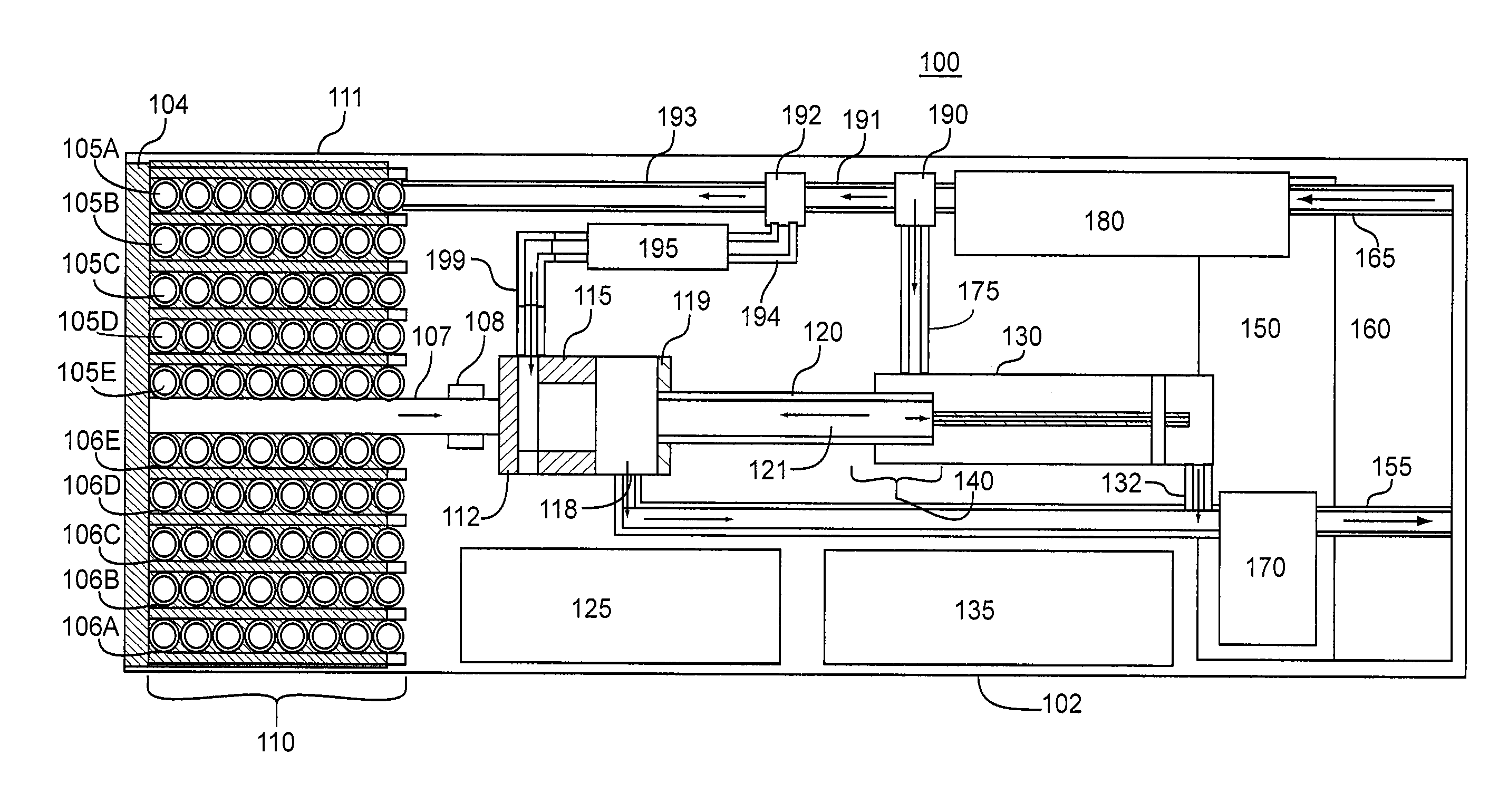
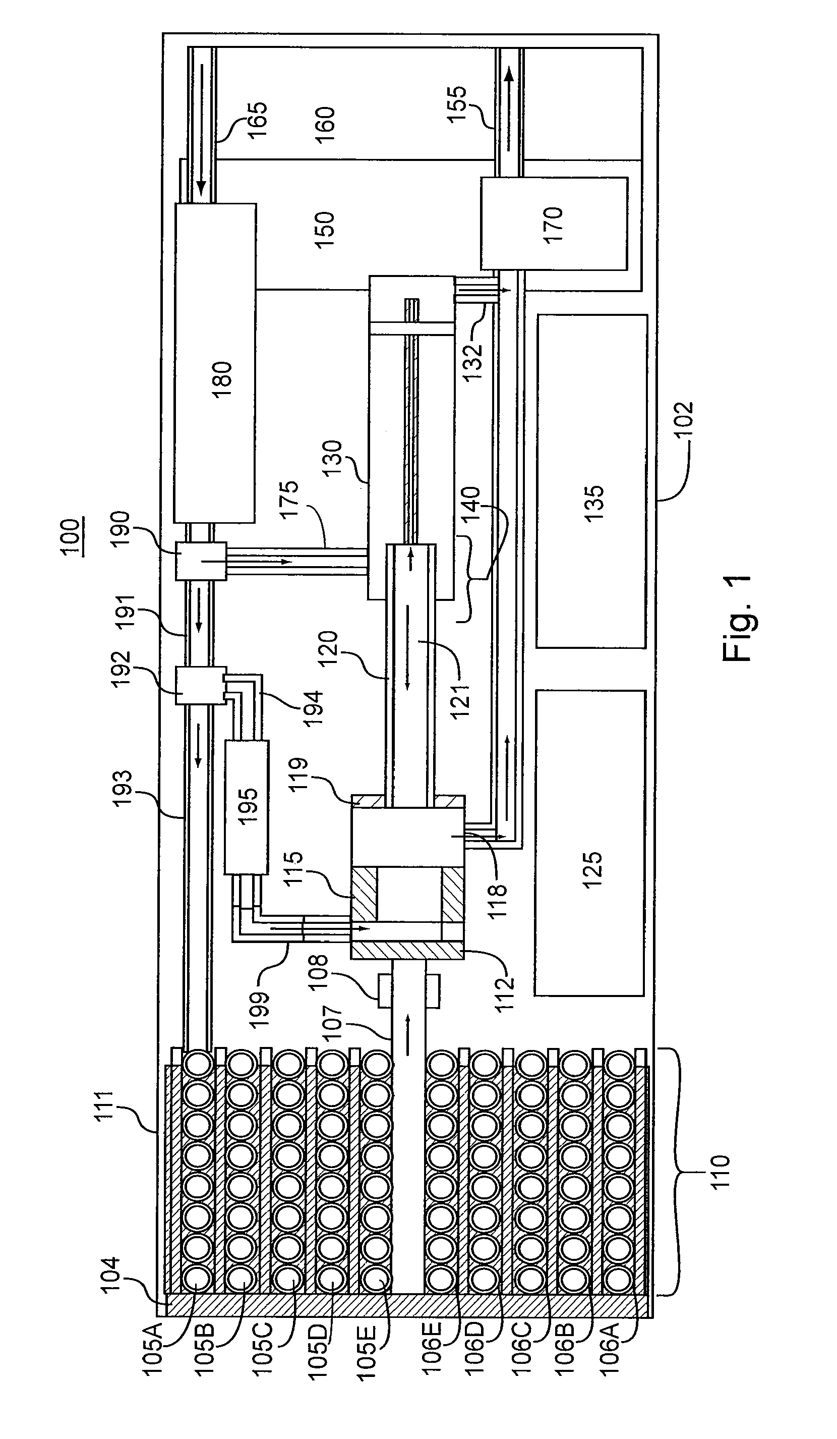
[0037]FIG. 1 shows a schematic view of a first embodiment of an ion mobility sensor system 100 in accordance with the present invention. Described generally, in this embodiment, a fluid, which is usually a carrier gas, enters the ion mobility sensor system 100 through channel 165 and is moved indirectly by a flow controller, such as pump 170, via the closed channel system including channels 175, 191, 193, 194, and 199, through a dryer 180, a first flow control unit 190, a channel 191, a second flow control unit 192, and a channel 193 into filters 105A-E of extraction sampler 110. Each filter 105A-E is constructed of a permeable membrane 106A-E. Extraction sampler 110 includes a chamber 111 in communication with a sample substance 104, which is often groundwater. Contaminants in the sample substance 104 permeate thro...


PUM


Abstract

An ion mobility sensor system including an ion mobility spectrometer and a differential mobility spectrometer coupled to the ion mobility spectrometer. The ion mobility spectrometer has a first chamber having first end and a second end extending along a first direction, and a first electrode system that generates a constant electric field parallel to the first direction. The differential mobility spectrometer includes a second chamber having a third end and a fourth end configured such that a fluid may flow in a second direction from the third end to the fourth end, and a second electrode system that generates an asymmetric electric field within an interior of the second chamber. Additionally, the ion mobility spectrometer and the differential mobility spectrometer form an interface region. Also, the first end and the third end are positioned facing one another so that the constant electric field enters the third end and overlaps the fluid flowing in the second direction.

Description

[0001]This invention was made with government support under Contract No. DE-AC05-00OR22725 awarded by the U.S. Department of Energy. The government has certain rights in the invention.BACKGROUND OF THE INVENTION[0002]1. Field of the Invention[0003]The present invention relates generally to ion mobility sensor systems. Specifically, one aspect of the present invention relates to an extraction sampler and an ion mobility sensor system that uses such an extraction sampler. A second aspect of the present invention relates to an ion mobility sensor system that includes an interface which can be applied between ion mobility spectrometry (IMS) and differential mobility spectrometry (DMS) technology.[0004]2. Discussion of Related Art[0005]Contaminated groundwater and its associated vapor are a major concern due to the persistence of certain pollutants such as dense non-aqueous phase liquids (DNAPLs). Chlorinated hydrocarbons constitute the major portion of DNAPLs and, as such, must be monit...

Claims


Application Information

Patent Timeline
Patent Type & Authority Patents(United States)
IPC IPC(8): H01J49/00
CPCG01N27/622
Inventor XU, JUNWATSON, DAVID B.WHITTEN, WILLIAM B.
Owner UT BATTELLE LLC
Why Eureka
Try Eureka