Surface acoustic wave resonator, surface acoustic wave oscillator, and surface acoustic wave module unit

a technology of surface acoustic wave and surface acoustic wave, which is applied in the direction of oscillator, piezoelectric/electrostrictive device details, piezoelectric/electrostrictive/magnetostrictive devices, etc., can solve the problem that the characteristics of the surface acoustic wave resonator cannot be satisfactorily obtained, and achieves the effect of reducing size, reducing q value and small siz

Active Publication Date: 2013-01-22
PANASONIC CORP +1
View PDF29 Cites 7 Cited by
  • Summary
  • Abstract
  • Description
  • Claims
  • Application Information

AI Technical Summary

Benefits of technology

[0014]In the first region at the center of the IDT, since the reflected waves are superposed with a small phase difference due to this weighting, the vibration displacement is maintained to be great. Since the reflection of surface acoustic waves to the first region from the second region and the third region can be enhanced, it is possible to enhance the confinement of vibration energy in the IDT, thereby improving the Q value.
[0045]According to this configuration, since the surface acoustic wave resonator having the enhanced Q value and the reduced size is mounted, it is possible to provide a surface acoustic wave module unit having a small size.

Problems solved by technology

When the number of pairs of electrode fingers in an IDT (Interdigital Transducer) including a comb-like electrode decreases so as to reduce the size of the surface acoustic wave resonator, there is a problem in that a decrease in Q value or an increase in CI (Crystal Impedance) value is caused and thus the characteristics of the surface acoustic wave resonator cannot be satisfactorily obtained.

Method used


Image

  • Surface acoustic wave resonator, surface acoustic wave oscillator, and surface acoustic wave module unit
  • Surface acoustic wave resonator, surface acoustic wave oscillator, and surface acoustic wave module unit
  • Surface acoustic wave resonator, surface acoustic wave oscillator, and surface acoustic wave module unit

Examples


first embodiment

[0116]A surface acoustic wave resonator according to a first embodiment of the invention will be described below.

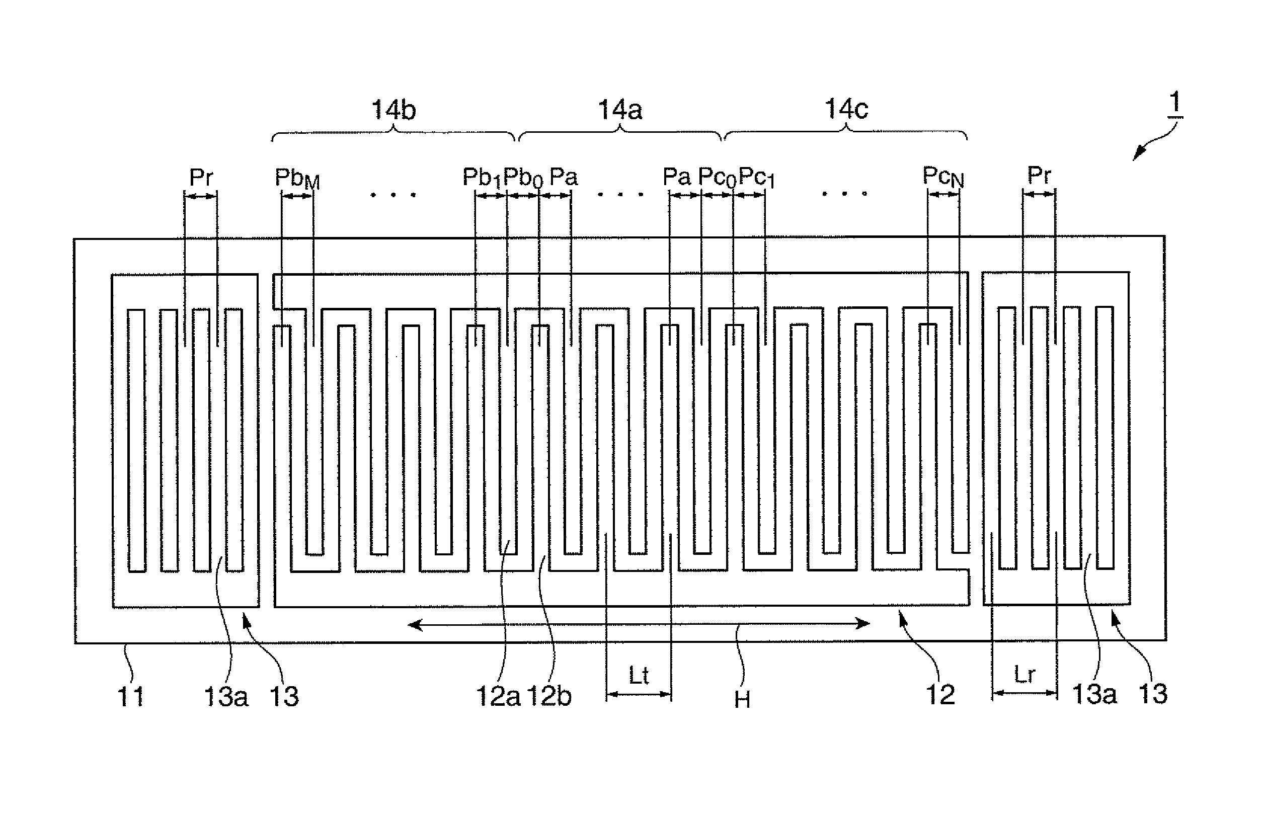
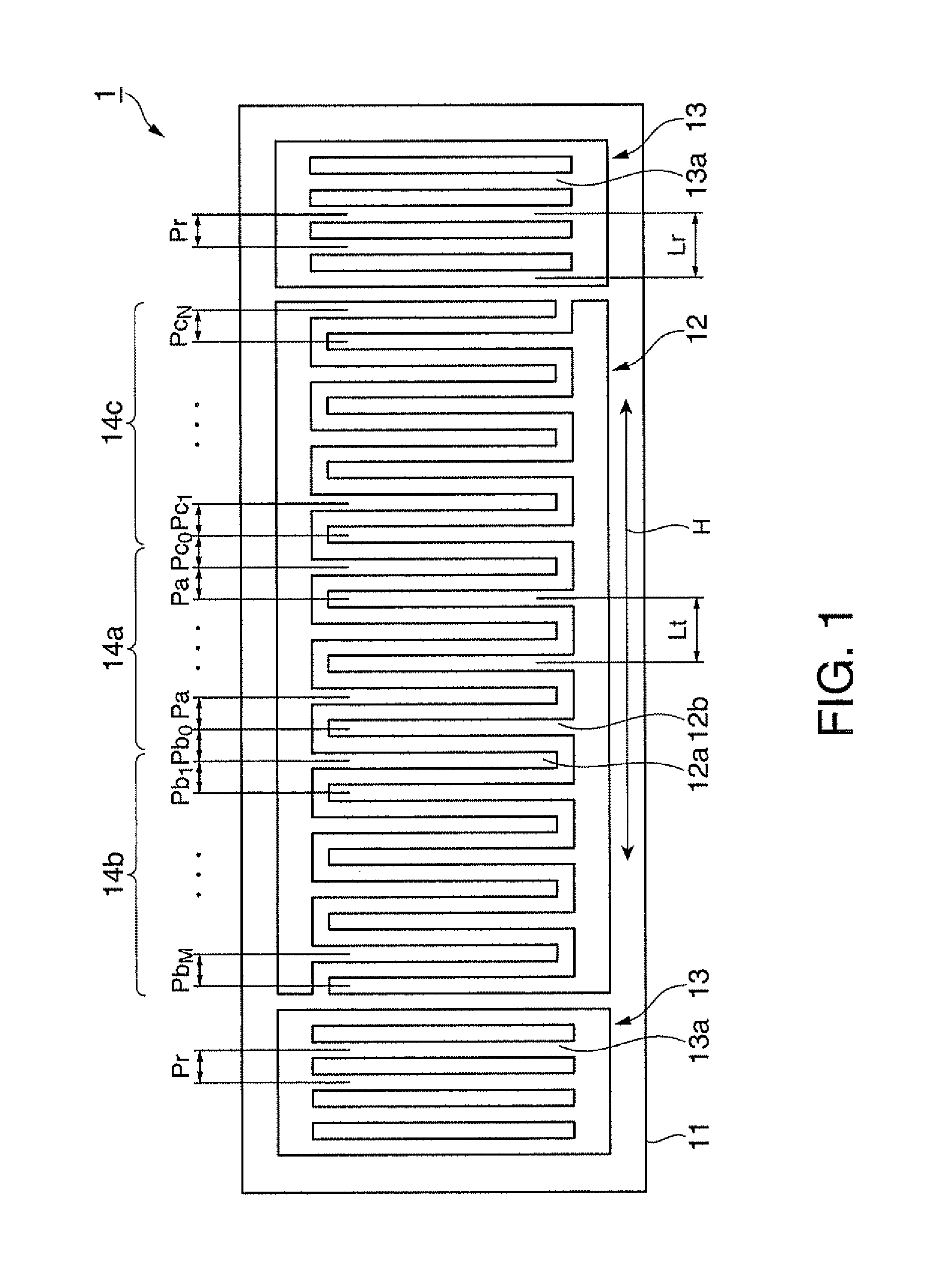
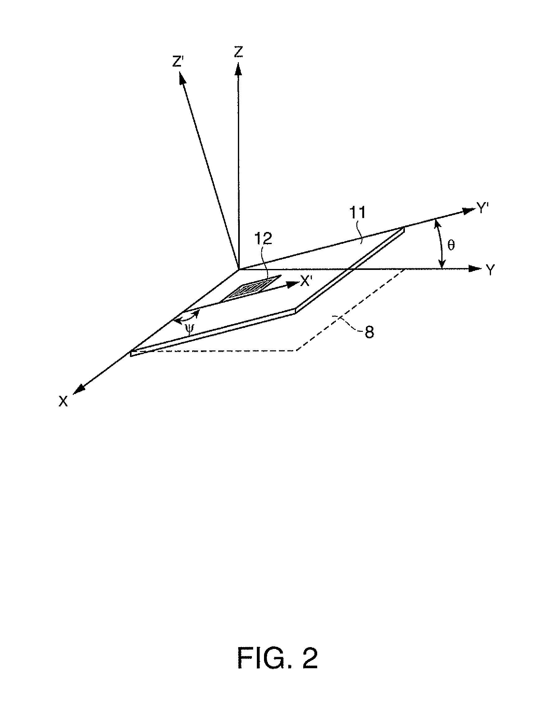
[0117]FIG. 1 is a plan view schematically illustrating the configuration of a surface acoustic wave resonator according to a first embodiment of the invention. FIG. 2 is a diagram illustrating a cutout angle of a crystal substrate and a traveling direction of surface acoustic waves. FIG. 3 is a diagram illustrating the relation between an electrode finger position and an electrode finger pitch in the surface acoustic wave resonator according to the first embodiment. FIG. 4 is a diagram illustrating the relation between the electrode finger position and the frequency in the surface acoustic wave resonator according to the first embodiment. FIG. 5 is a diagram illustrating the relation between the electrode finger position and a variation in electrode finger pitch in the surface acoustic wave resonator according to the first embodiment.

[0118]As shown in FIG. 1, the surface ...

modification 1

(Modification 1)

[0189]FIG. 16 is a diagram illustrating the relation between the electrode finger position and the variation in electrode finger pitch in a surface acoustic wave resonator according to Modification 1. Modification 1 is different from the first embodiment, in the variation in electrode finger pitch in the reflectors.

[0190]The electrode finger pitch gradually increases from a part adjacent to the first region to both edges of the IDT and the variation in electrode finger pitch at both edges of the IDT is 1.2%. The variation in electrode finger pitch in the reflectors is 2.0%.

[0191]In the first embodiment, the variation in electrode finger pitch in the reflectors is set to be smaller than the variation in electrode finger pitch at the edges of the IDT. However, as shown in FIG. 16, the variation in electrode finger pitch in the reflectors may be set to be greater than the variation in electrode finger pitch at the edges of the IDT.

[0192]The same advantages as the first ...

modification 2

(Modification 2)

[0193]FIG. 17 is a diagram illustrating the relation between the electrode finger position and the electrode finger pitch in a surface acoustic wave resonator according to Modification 2.

[0194]Modification 2 is different from the first embodiment, in that the electrode finger pitches (frequencies) at the edges of the second region and the third region of the IDT are different from each other.

[0195]The electrode finger pitch in the first region of the IDT is fixed to Pa. The electrode finger pitch in the second region varies in the range of Pb0 to PbM. The electrode finger pitch in the second region varies so as to gradually increase from a part adjacent to the first region to an edge of the IDT. The electrode finger pitch in the third region varies in the range of Pc0 to PcN. The electrode finger pitch in the third region varies so as to gradually increase from a part adjacent to the first region to the other edge of the IDT. The electrode finger pitches at the edges...


PUM


Abstract

It is possible to reduce the size of a surface acoustic wave (SAW) resonator by enhancing a Q value. In a SAW resonator in which an IDT having electrode fingers for exciting SAW is disposed on a crystal substrate, the IDT includes a first region disposed at the center of the IDT and a second region and a third region disposed on both sides of the first region. A frequency is fixed in the first region and a portion in which a frequency gradually decreases as it approaches an edge of the IDT is disposed in the second region and the third region. When the frequency of the first region is Fa, the frequency at an edge of the second region is FbM, and the frequency at an edge of the third region is FcN, the variations in frequency are in the ranges of 0.9815<FbM / Fa<0.9953 and 0.9815<FcN / Fa<0.9953, respectively.

Description

TECHNICAL FIELD[0001]The present invention relates to a surface acoustic wave resonator employing a piezoelectric substrate, a surface acoustic wave oscillator, and a surface acoustic wave module unit.BACKGROUND ART[0002]Conventionally, surface acoustic wave resonators using surface acoustic waves (SAW) have been widely used in electronic apparatuses.[0003]With the recent spread of portable devices, there has been a demand for a decrease in the size of surface acoustic wave resonators used therein. When the number of pairs of electrode fingers in an IDT (Interdigital Transducer) including a comb-like electrode decreases so as to reduce the size of the surface acoustic wave resonator, there is a problem in that a decrease in Q value or an increase in CI (Crystal Impedance) value is caused and thus the characteristics of the surface acoustic wave resonator cannot be satisfactorily obtained.[0004]As a countermeasure, for example, PTL 1 discloses a surface acoustic wave resonator in whi...

Claims


Application Information

Patent Timeline
Patent Type & Authority Patents(United States)
IPC IPC(8): H01L41/04H03H9/64H03B5/30
CPCH03H9/02551H03H9/0547H03H9/1071H03H9/14535H03H9/643H03H9/02543H03H9/02661H03H9/14517H03H9/25H03B5/32H03H9/02685
Inventor YAMANAKA, KUNIHITO
Owner PANASONIC CORP
Why Eureka
Try Eureka