Modeling of cell delay change for electronic design automation

a technology of electronic design automation and delay change, applied in the field of electronic design automation, can solve the problems of finer granularity, inconsistent results, and cost of adding cells to the library

Active Publication Date: 2013-01-22
SYNOPSYS INC
View PDF35 Cites 10 Cited by
  • Summary
  • Abstract
  • Description
  • Claims
  • Application Information

AI Technical Summary

Problems solved by technology

Adding cells to the library is costly, as each cell in the library is prequalified for manufacturability and other factors.
MGL, similar to the within-cell transistor-level biasing, results in finer levels of granularity in delay-leakage trade-off on the cell level.
Previous studies, however, reported inconsistent findings, with some showing noticeable additional leakage reduction and others observing very little advantage by using finer levels of granularity.
While previous works have primarily focused on modeling the delay itself, they are relatively ineffective in capturing the changes in delay.
Also, modeling for the purposes of library characterization can be prohibitively expensive using prior models because of the explosively huge number of cell variants that might be needed in a robust library to optimization processes.

Method used


Image

  • Modeling of cell delay change for electronic design automation
  • Modeling of cell delay change for electronic design automation
  • Modeling of cell delay change for electronic design automation

Examples


Embodiment Construction

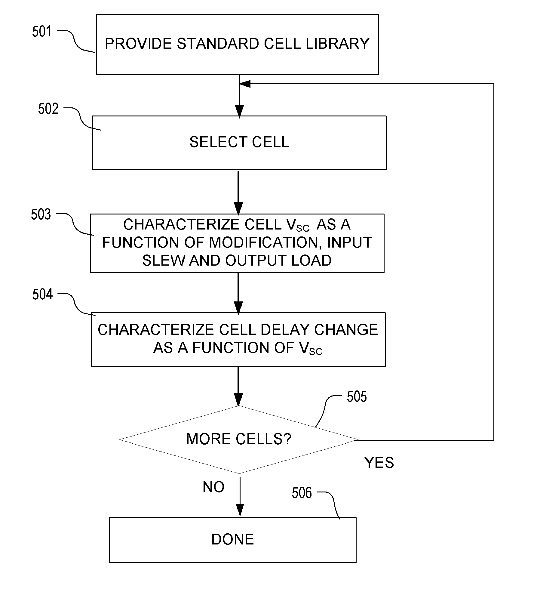
[0041]A detailed description of embodiments of the present invention is provided with reference to the FIGS. 1-15.

[0042]A phenomenological model derived from device equations with empirical fitting parameters to model percentage changes in delay as a result of gate length bias is described. The model can be extended to any type of cell modification, such as threshold voltage doping, gate shape changes, cell width changes, and so on, that can be used for optimizations constrained by delay. The model focuses on capturing the percentage delay change as a function of gate length change or other change (i.e., bias) over wide, practical ranges of input slews and output capacitances that are typically used in library characterization. The model can be derived based on physical device equations with empirical fitting parameters for improved accuracy. A physically based parameter is introduced that can be determined efficiently based on cell modifications and that correlates with delay chang...


PUM


Abstract

An integrated circuit design optimization procedure to modify a cell feature, such as gate length, models changes in delay as a result of the modification. In the delay change calculation, a characteristic of an event in cell switching behavior, such as the output short-circuit voltage VSC, is determined for the modified cell, where changes in the determined characteristic correlate with changes in delay of the cell due to the modification. Next, a value for delay of the modified cell is determined as a function of the determined characteristic of the event. The procedure can be applied after placement and routing. A timing-constrained, leakage power reduction is described using the delay change model.

Description

BACKGROUND[0001]1. Field of the Invention[0002]The present invention relates to electronic design automation (EDA), and to modeling delay changes arising for example from implementation of changes in cells of an integrated circuit design for performance optimization.[0003]2. Description of Related Art[0004]One approach to EDA supported design is based on the definition of an integrated circuit using a computer system as a netlist of circuit elements. Also, a cell library is provided that specifies characteristics of cells available for use in a physical implementation using a given technology of the circuit elements in the netlist. The entries in the library include layout data, performance data such as delay models and power models, and other supporting information. To implement the netlist, cells are selected from the library, placed in a layout space, and interconnections are defined among the cells. The selection of cells, placement of cells and defining interconnections among t...

Claims


Application Information

Patent Timeline
Patent Type & Authority Patents(United States)
IPC IPC(8): G06F17/50
CPCG06F17/5036G06F17/5009G06F17/5022G06F2217/84G06F2119/12G06F30/367G06F30/20G06F30/33G06F30/3308
Inventor TANG, QIAN-YINGCHEN, QIANGTIRUMALA, SRIDHAR
Owner SYNOPSYS INC
Why Eureka
Try Eureka