Structure for disposing clutch control apparatus in power unit for saddle-ride type vehicle

a technology of power unit and clutch control, which is applied in the direction of clutches, fluid actuated clutches, non-mechanical actuated clutches, etc., can solve the problems of clutch control apparatus cooling down problems, clutch control apparatus difficulty in receiving air flow, and vehicle body length in front-and-rear direction, so as to achieve the effect of receiving air flow more efficiently and improving cooling performan

Active Publication Date: 2013-01-29
HONDA MOTOR CO LTD
View PDF21 Cites 4 Cited by
  • Summary
  • Abstract
  • Description
  • Claims
  • Application Information

AI Technical Summary

Benefits of technology

[0007]The present invention is made in view of the above-described circumstances. Accordingly, an object of an embodiment of the present invention is to provide a structure for disposing a clutch control apparatus in a power unit for a saddle-ride type vehicle. The structure prevents the engine main body from becoming longer in the front-and-rear direction. At the same time, the structure allows the clutch control apparatus to receive the air flow more efficiently and thus achieve higher cooling performance for the clutch control apparatus.

Problems solved by technology

The structure of this type tends to result in a larger vehicle body length in the front-and-rear direction.
In the structure of this type, however, the clutch control apparatus has difficulty in receiving an air flow because the frame members and other component parts that exist around the clutch control apparatus block the air flow.
Accordingly, the cooling-down of the clutch control apparatus becomes a problem.

Method used


Image

  • Structure for disposing clutch control apparatus in power unit for saddle-ride type vehicle
  • Structure for disposing clutch control apparatus in power unit for saddle-ride type vehicle
  • Structure for disposing clutch control apparatus in power unit for saddle-ride type vehicle

Examples


Embodiment Construction

[0040]A mode of carrying out the present invention will be described below. The descriptions will be based on an embodiment of the present invention. The embodiment will be described with reference to accompanying drawings.

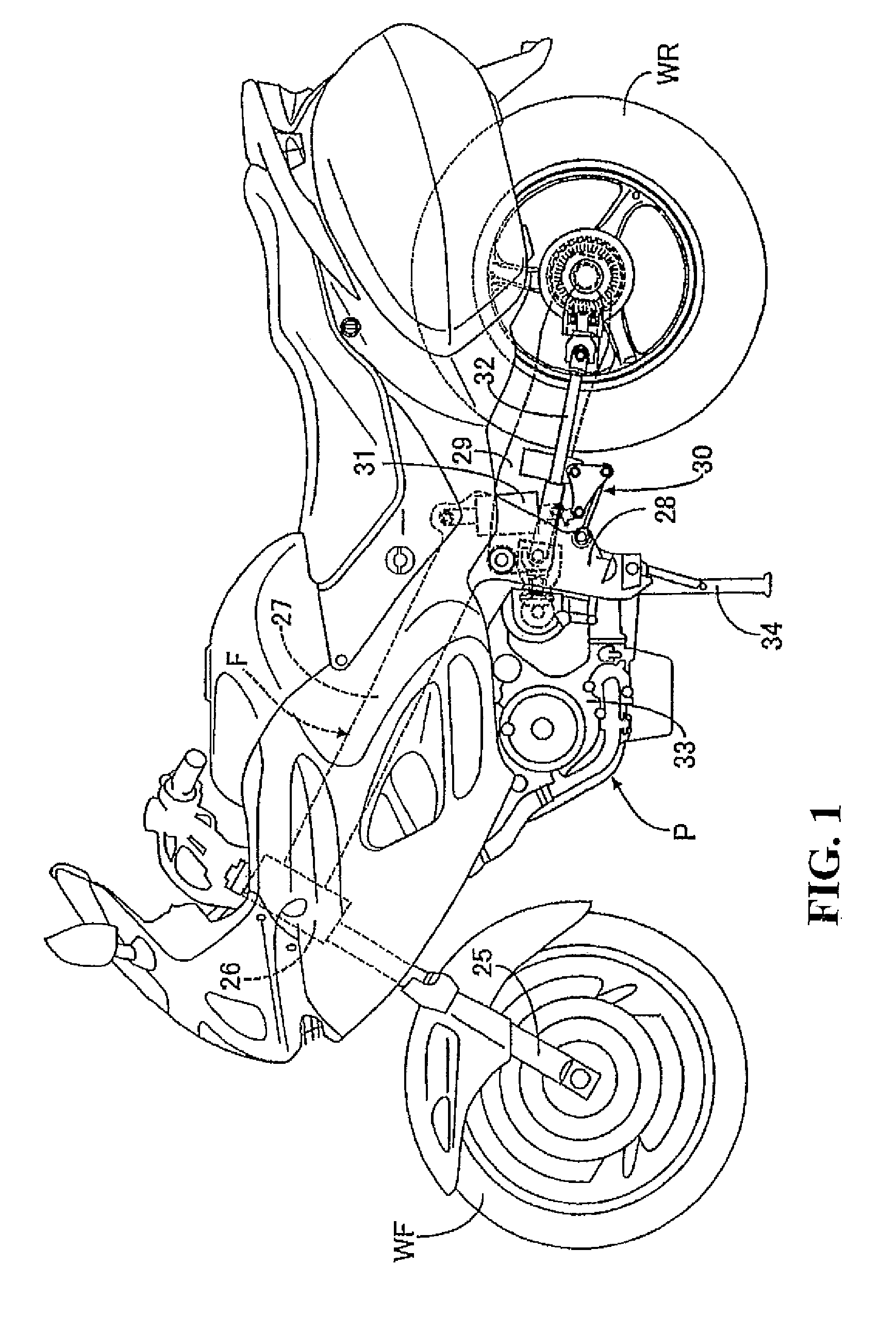
[0041]FIGS. 1 to 15 illustrate an embodiment of the present invention. Referring to FIG. 1, a vehicle-body frame F of a motorcycle—a saddle-ride type vehicle—includes a head pipe 26, a right-and-left pair of main frames 27, a right and left pair of pivot plates 28. The head pipe 26 rotatably supports a steerable front fork 25. The front fork 25 pivotally supports a front wheel WF. The main frames 27 extend from the head pipe 26 downwards to the rear. The pivot plates 28, which extend downwards, are provided contiguously from the rear end of respective main frames 27. A swing arm 29, which is swingably supported at its front end by the pivot plates 28, pivotally supports a rear wheel WR at its rear portion. In addition, a linkage 30 is disposed between the lower po...


PUM


Abstract

A clutch control apparatus for receiving an air flow more easily and to obtain a higher cooling performance in a power unit for a saddle-ride type vehicle while avoiding the size of the main engine body becoming larger in the front-and-rear direction. The power unit includes a clutch apparatus installed in a clutch chamber. The clutch apparatus is disposed in the course of power transmission from a crankshaft to a drive wheel. The clutch chamber is formed between a crankcase and a clutch cover that is coupled to a side surface of the crankcase. A clutch control apparatus that controls the switching of the connection and disconnection actions of a clutch apparatus is attached to the outer surface of a clutch cover in a position at a side of a cylinder block.

Description

CROSS-REFERENCE TO RELATED APPLICATIONS[0001]The present application claims priority under 35 USC 119 to Japanese Patent Application No. 2007-256957 filed on Sept. 29, 2007 the entire contents of which are hereby incorporated by reference.BACKGROUND OF THE INVENTION[0002]1. Field of the Invention[0003]The present invention relates to a power unit for a saddle-ride type vehicle. In the power unit, a clutch apparatus is disposed in the course of power transmission between a crankshaft and a drive wheel for switching the connection and disconnection of the transmission of torque to the drive wheel from the crankshaft rotatably supported by a crankcase that forms a part of an engine main body. The clutch apparatus is installed in a clutch chamber formed between the crankcase and a clutch cover coupled to a side surface of the crankcase. The present invention, in particular, relates to an improved structure for disposing a clutch control apparatus.[0004]2. Description of Background Art[0...

Claims


Application Information

Patent Timeline
Patent Type & Authority Patents(United States)
IPC IPC(8): F16D25/10F16D25/06
CPCF16D25/0638F16D25/10F16D21/06
Inventor FUJIMOTO, YASUSHIOGASAWARA, ATSUSHI
Owner HONDA MOTOR CO LTD
Why Eureka
Try Eureka