Method of assisting piloting at low altitude

Active Publication Date: 2013-01-29
EUROCOPTER
View PDF33 Cites 2 Cited by
  • Summary
  • Abstract
  • Description
  • Claims
  • Application Information

AI Technical Summary

Benefits of technology

[0033]An object of the present invention is thus to propose a method of assisting piloting at low altitude that makes it possible to generate a path that can be tolerated in particular by people who are physically weakened.
[0035]According to the invention, in a method of assisting piloting an aircraft at low altitude over a terrain, during a first stage, a framework is constructed from at least one main segment of given corridor width that extends in a horizontal projection over a model of said terrain between successive first and second waypoints determined by an operator, and then during a second stage, a setpoint flight path is constructed with the help of the framework. The setpoint flight path is generated so as to rest on the framework, in particular so as to make it possible to provide optimized level flight.
[0046]The method of the invention thus serves to reduce the altitude at which the rotorcraft flies, while nevertheless flying in level stages in order to avoid harming an accident victim.
[0047]Flying in this way at successive levels at a setpoint height above the ground also enables the pilot to be physiologically comfortable. The pilot can thus follow a flight path that provides stages of level flight during which the work load on the pilot is reduced.
[0063]An operator may seek to minimize flying time at one or more high altitudes. Thus, the invention makes it possible to shorten the secondary segments that pass via high points.
[0076]Thereafter, for said framework being moved longitudinally through a given stepsize and in iterative manner over a given distance, with the value of said expression E being recalculated on each step, the value of said expression E is minimized during the second stage by using the framework that gave rise to a minimum value for said expression.

Problems solved by technology

Although very advantageous and effective, that method does not seek to establish a path to be followed by an aircraft in order to satisfy precise constraints.

Method used


Image

  • Method of assisting piloting at low altitude
  • Method of assisting piloting at low altitude
  • Method of assisting piloting at low altitude

Examples


Embodiment Construction

[0106]Elements that are present in more than one of the figures are given the same references in each of them.

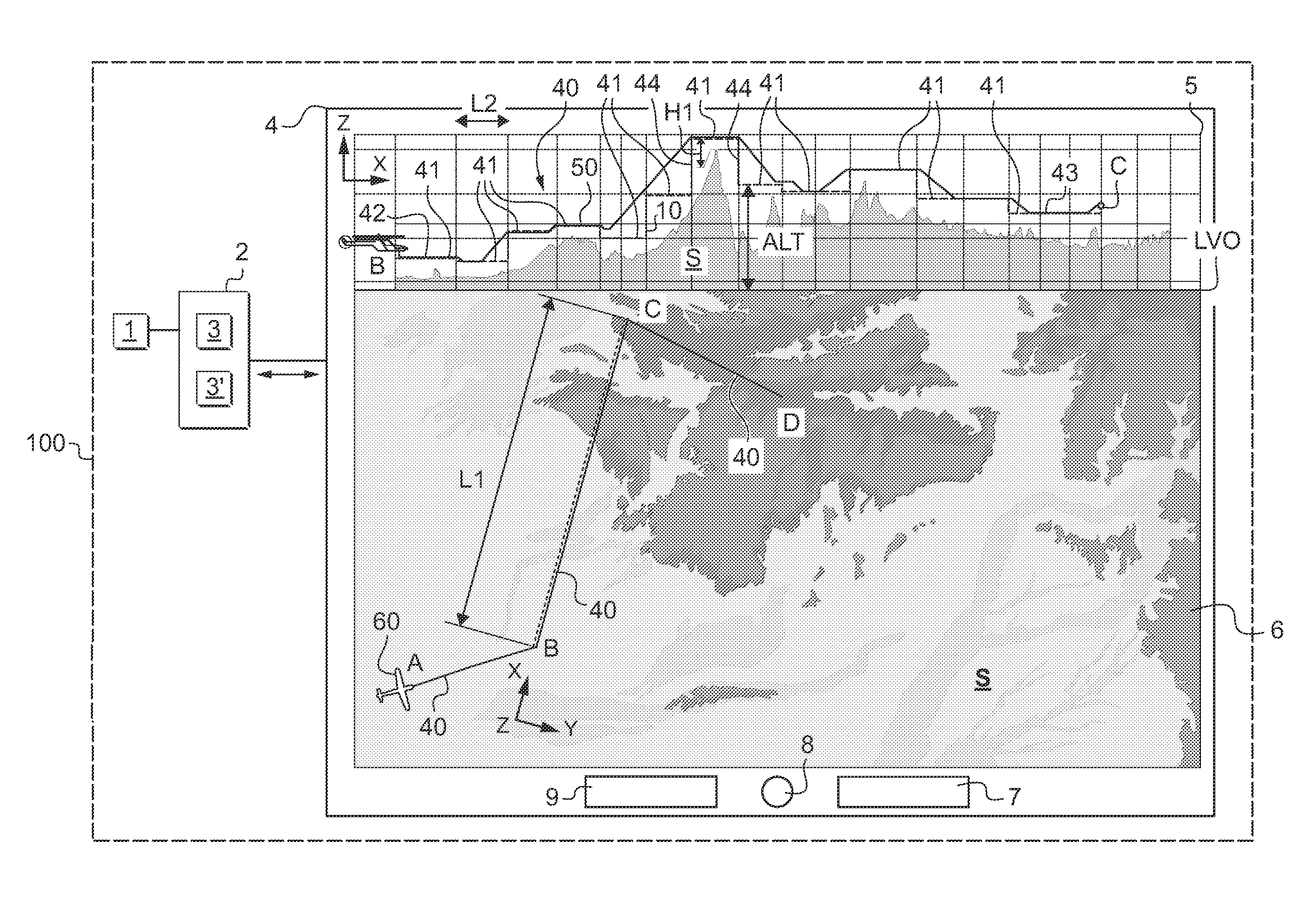
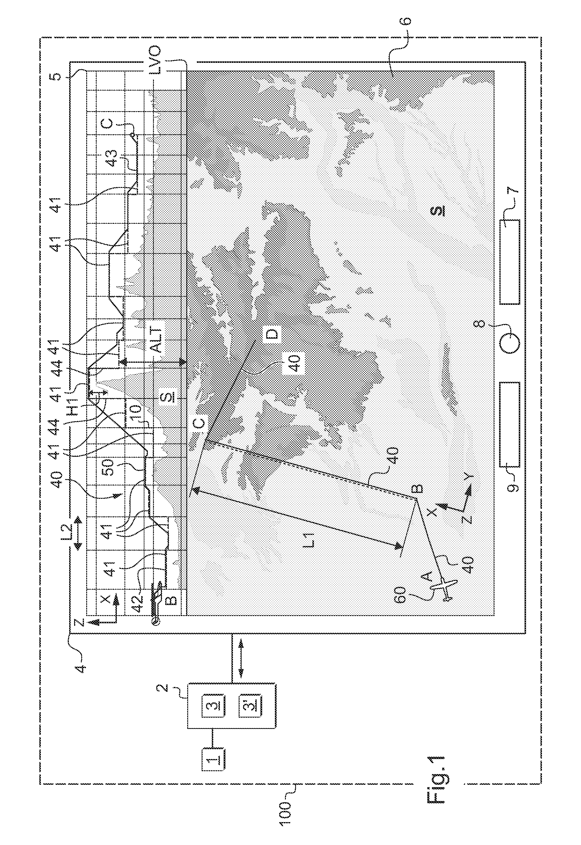
[0107]FIG. 1 shows three mutually orthogonal directions X, Y, and Z.

[0108]The first direction X is said to be longitudinal and the second direction Y is said to be transverse.

[0109]Finally, the third direction Z is said to be in elevation.

[0110]FIG. 1 shows a device suitable for implementing the method of the invention.

[0111]The device comprises computer means 2 provided with a processor 3, e.g. a microprocessor, and a memory 3′.

[0112]The computer means 2 communicate with a database 1 containing a digital terrain model, such as a level 2 DTED® model, so as to cause display means 4 to display a horizontal projection 6 of said terrain S onto a plane (X, Y) representing a plan view of the terrain, together with a vertical section 5 of the terrain S taken along the route to be followed in a plane (X, Y).

[0113]The database 1, the computer means 2, and the display means 4 may form...


PUM


Abstract

A method of assisting the piloting of an aircraft (60) at low altitude over terrain (S), in which method, during a first stage, a framework (10) is constructed from at least one main segment (40) and during a second stage a setpoint flight path (50) is constructed. More precisely, during the first stage, said main segment (40) is subdivided automatically into a plurality of secondary segments (41, 42, 43), each of said secondary segments (41) being situated at the same setpoint height above the highest point of the underlying terrain, with two adjacent secondary segments (41) being in alignment or connected together by a bar (44) that extends vertically in a vertical section.

Description

CROSS-REFERENCE TO RELATED APPLICATION[0001]This application claims the benefit of FR 09 03119 dated Jun. 26, 2009, the disclosure of which is incorporated herein by reference.FIELD OF THE INVENTION[0002]The present invention relates to a method of assisting piloting at low altitude, enabling the crew of an aircraft to prepare and follow a safe flight plan, outside instrument-flying infrastructures.[0003]The invention thus lies in the field of navigation and flight management systems for an aircraft, and more particularly a helicopter, which field usually covers the functions of positioning, preparing a flight plan, and generating a flight path.[0004]It should be observed that the term “flight plan” designates a theoretical route to be followed by an aircraft in order to go from a first waypoint to a second waypoint, and then possibly from the second waypoint to a third waypoint, and so on.[0005]In addition, the term “flight path” is used to designate the path to be followed by the ...

Claims


Application Information

Patent Timeline
Patent Type & Authority Patents(United States)
IPC IPC(8): G06F7/70
CPCG01C23/00G05D1/0646G08G5/0086G08G5/0021
Inventor FILIAS, FRANCOIS-XAVIERGILLET, MARIANNE
Owner EUROCOPTER
Why Eureka
Try Eureka