
FC fan flow measurement system using a curved inlet cone and pressure sensor

a technology of flow measurement system and inlet cone, which is applied in the direction of positive displacement liquid engine, heating type, lighting and heating apparatus, etc., can solve the problems of affecting the flow of air through the fan, and affecting the flow of air

Active Publication Date: 2013-02-05
TRANE INT INC
View PDF19 Cites 5 Cited by
  • Summary
  • Abstract
  • Description
  • Claims
  • Application Information

AI Technical Summary

Benefits of technology

The patent text describes a way to measure the amount of air flow through a centrifugal fan using a single pressure gauge without creating a pressure drop or flow obstruction. The method is simple and can be used with fans that have curved fan blades. It also provides a way to protect the pressure receiver from damage while maintaining a neat appearance.

Problems solved by technology

The volume of air flowing through a fan can be difficult to determine because the air velocity usually varies depending on the location of the air streams within the fan or within the ducts leading to or from the fan.
Inserting such pressure taps across the flow path, however, can disrupt and restrict the flow.
Such an approach, however, can present an undesirable flow restriction and requires multiple pressure taps to sense the pressure drop across the restriction.

Method used


Image

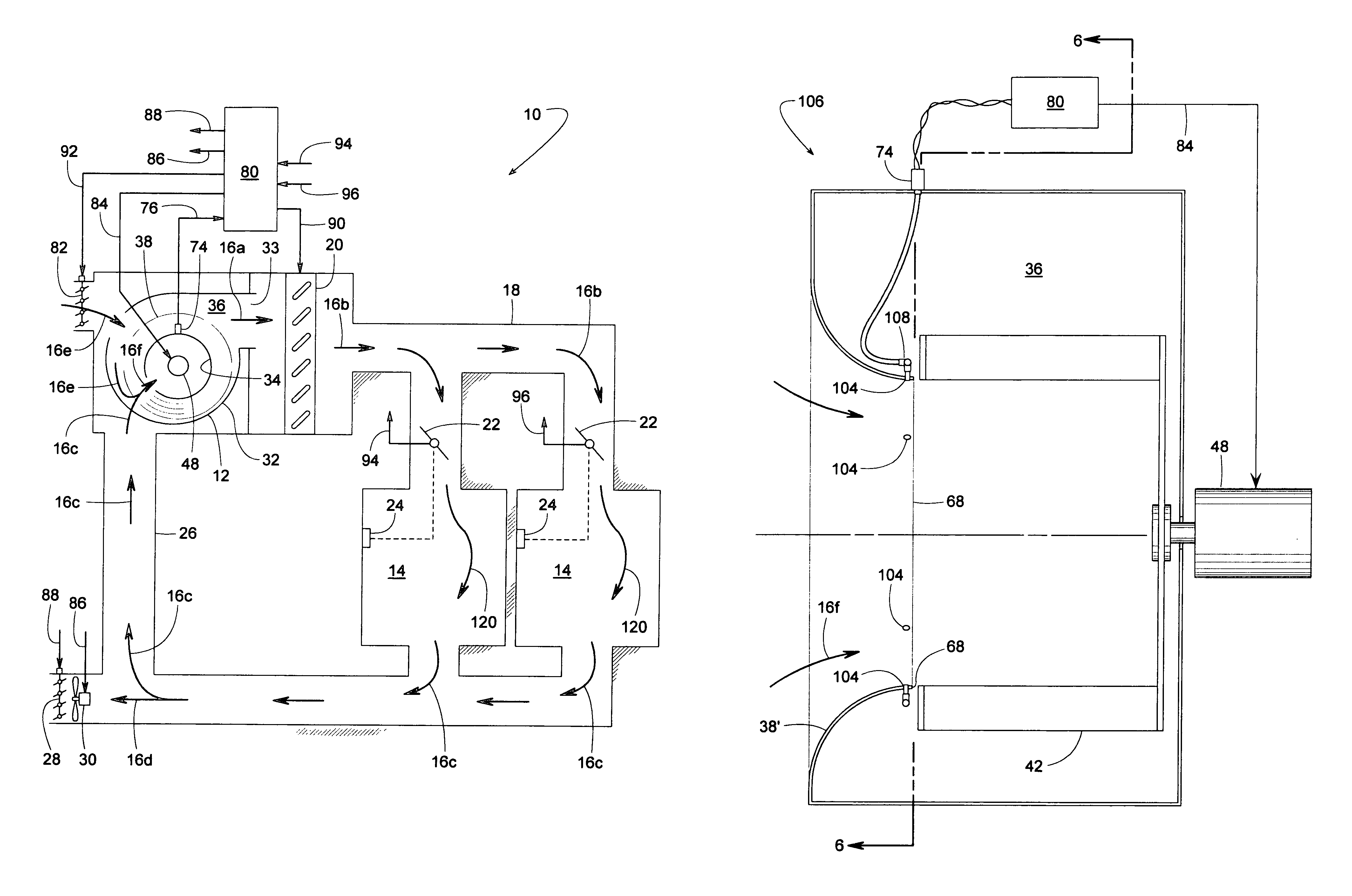
  • FC fan flow measurement system using a curved inlet cone and pressure sensor
  • FC fan flow measurement system using a curved inlet cone and pressure sensor
  • FC fan flow measurement system using a curved inlet cone and pressure sensor

Examples


Embodiment Construction

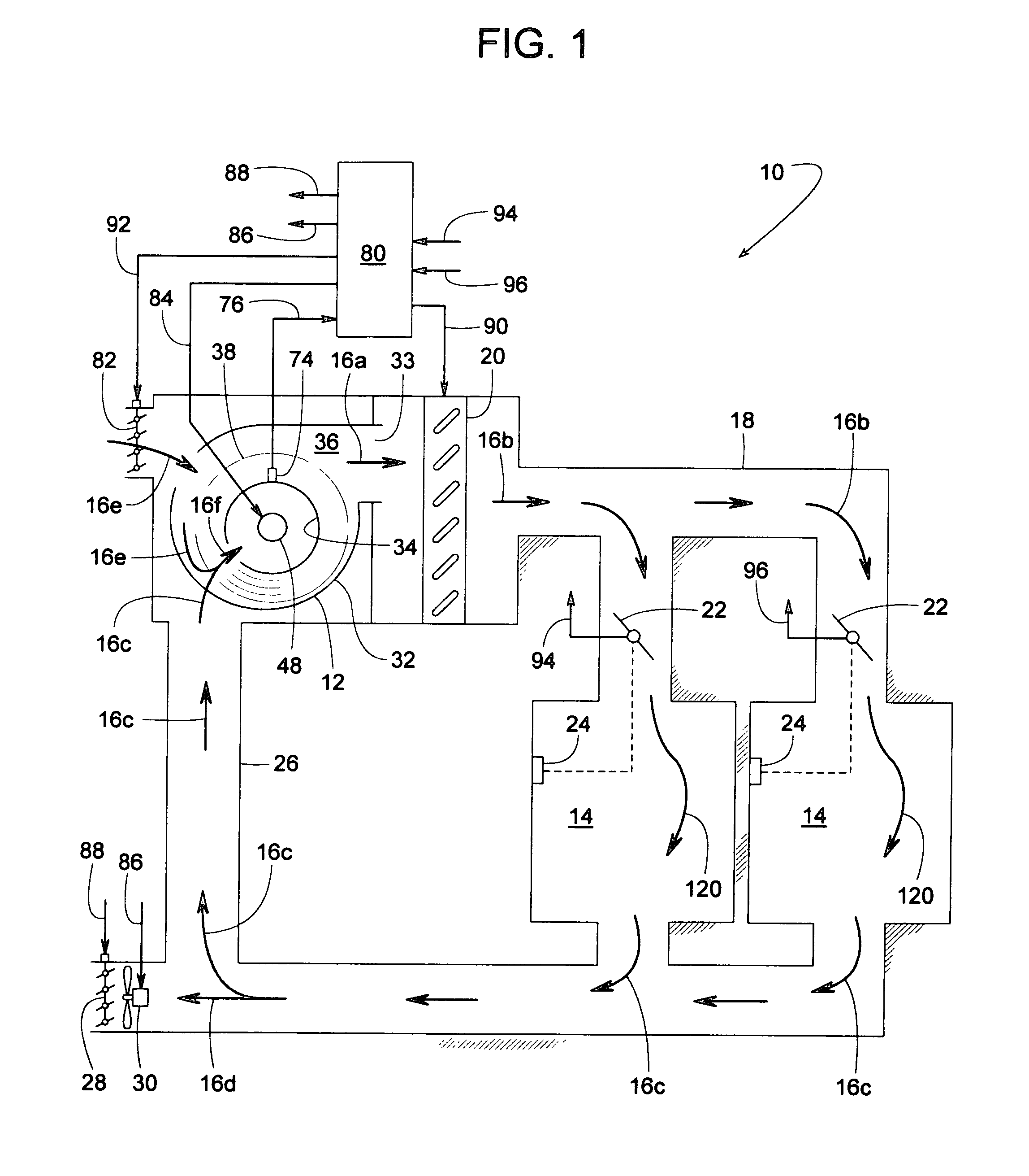
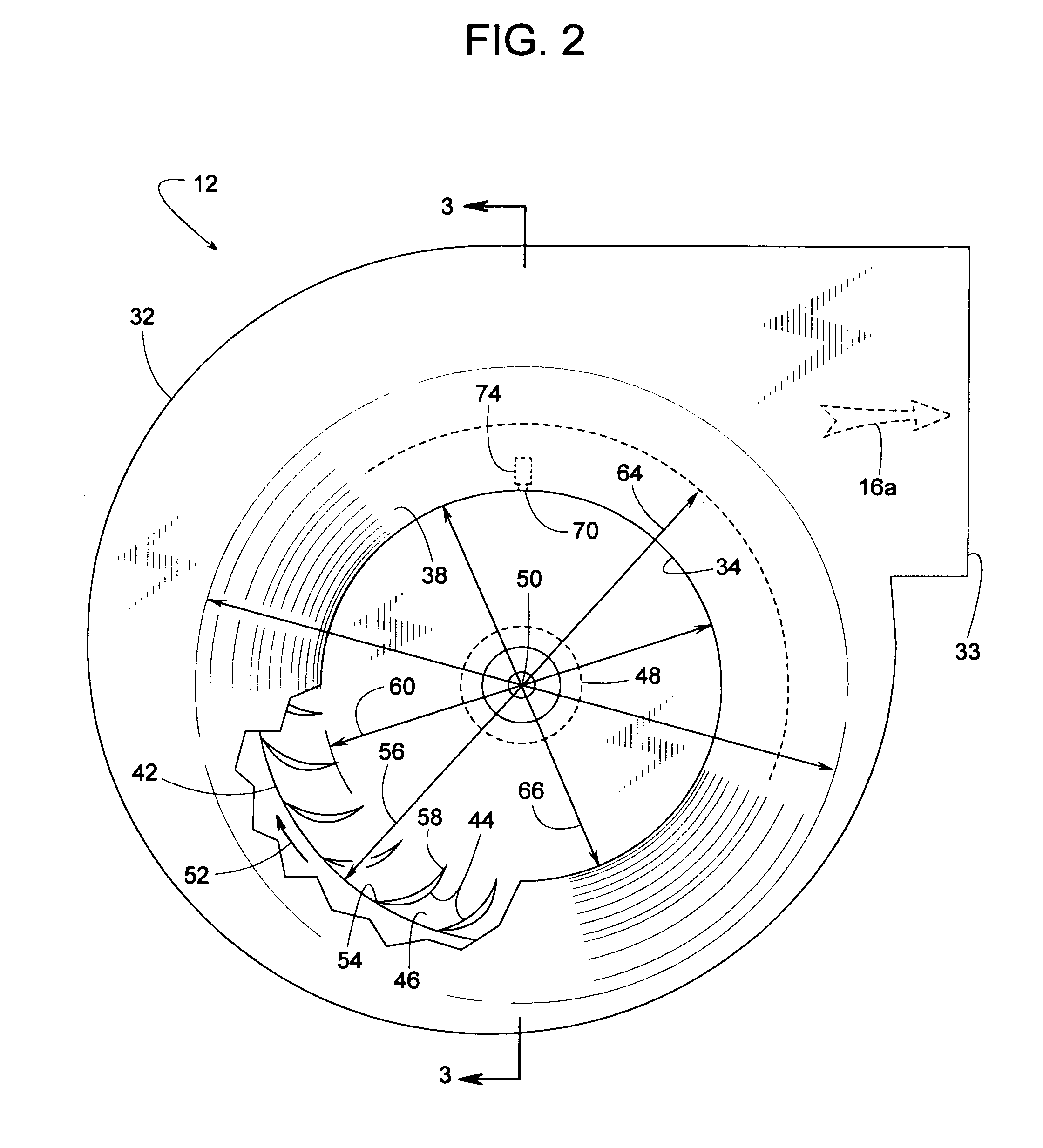
[0022]FIG. 1 schematically illustrates one example of a fan system 10 with a centrifugal fan 12 with additional views of fan 12 being shown in FIGS. 2 and 3. A novel means for determining the total volume airflow rate through fan 12 is used, in some cases, to help ensure that fan 12 delivers the proper amount of conditioned air and / or fresh outside air to a plurality of comfort zones 14, such as rooms or other designated areas of a building. Examples of conditioned air include, but are not limited to, air that has been heated, cooled, filtered, humidified, dehumidified, and various combinations thereof.

[0023]In the illustrated example, fan 12 discharges a current of discharge air 16a that is known as supply air 16b as a supply air duct 18 conveys the air to comfort zones 14. In this particular example, a heat exchanger 20 heats, cools, or otherwise conditions the current of air moved by fan 12. To meet the individual conditioned-air demands of zones 14, a plurality of adjustable VAV...


PUM


Abstract

An airflow volume sensing system for determining the flow rate through a fan includes a curved inlet cone with a pressure sensor at the minimum diameter of the cone, wherein the flow volume sensing system is particularly suited for FC centrifugal fans (centrifugal fans with forward curved fan blades). With an FC fan, the minimum diameter of the inlet cones interior surface is adjacent the fan wheel, and the static pressure there is at a minimum value. A predetermined relationship between the static gage pressure at that point and the volume flow rate through the fan is applied regardless of variables such as fan speed, fan housing geometry, supply air duct configurations, return air duct configurations, location of various heat exchangers or filters, etc. In some examples, a single pressure sensor senses an average of a plurality of pressure taps wherein each tap is at approximately the same minimum pressure.

Description

BACKGROUND OF THE INVENTION[0001]1. Field of the Invention[0002]The subject invention generally pertains to centrifugal fans and more specifically to flow measuring systems for such fans.[0003]2. Description of Related Art[0004]The volume of air flowing through a fan can be difficult to determine because the air velocity usually varies depending on the location of the air streams within the fan or within the ducts leading to or from the fan. In some cases, a series of pressure taps distributed across the flow path provides a means for integrating the air's velocity profile, from which the total airflow volume can be determined. Inserting such pressure taps across the flow path, however, can disrupt and restrict the flow.[0005]In other cases, the air is directed through a certain flow restriction for which there is a known relationship between the volume airflow rate and the resulting pressure drop across the restriction. Such an approach, however, can present an undesirable flow res...

Claims


Application Information

Patent Timeline
Patent Type & Authority Patents(United States)
IPC IPC(8): F01D25/00F24F11/02G01F1/34
CPCF04D27/001F04D29/4226G01F1/34G01F1/36F05D2270/301
Inventor SMILEY, III, WILLIAM A.REYNOLDS, BRIAN L.
Owner TRANE INT INC
Learn More