Gantry rolling floor

a technology of gantry and rolling floor, which is applied in the direction of radiation therapy, electrodes and associated parts, therapy, etc., can solve the problems of insecurity of patients, device damage, and high energy doses for conventional radiotherapy to reach and destroy deep tumours, so as to avoid damage to the irradiation unit

Active Publication Date: 2013-02-05
ION BEAM APPL
View PDF9 Cites 48 Cited by
  • Summary
  • Abstract
  • Description
  • Claims
  • Application Information

AI Technical Summary

Benefits of technology

[0037]Preferably, said security means are adapted to absorb a circular motion of the gantry of at least 5° for avoiding any damage to the irradiation unit.

Problems solved by technology

The main drawback of that method is that healthy cells surrounding tumour cells are irradiated in the same time, damaging these healthy cells which may cause atrophy or several secondary effects, such as the release of secondary tumours.
Moreover, conventional radiotherapy often needs relatively high energy doses to reach and destroy deep tumours, since the photon energy traversing tissues is rapidly absorbed.
This configuration may give a feeling of insecurity to the patient.
In case of blocking or derailment of a sprocket, such a device could be seriously damaged.
Nevertheless, there still appears a gap between the nozzle and the moving floor in the area where the telescopic cylinder is extended.
Nevertheless, such a plant is not esthetic since almost all the inside of the gantry is visible, which may give a feeling of fear to the patient.
For this reason, a control system for each panel is needed which complicates the overall system.
The covers have the drawback to provide a flexible frame between the spaces created comprised between the caterpillars.
Moreover a blocking of a rolling up machine can occur during the rolling up or the unrolling of the cover which can damage this cover or the fixation of the caterpillars.

Method used


Image

  • Gantry rolling floor
  • Gantry rolling floor
  • Gantry rolling floor

Examples


Embodiment Construction

[0046]The present invention provides a particle therapy apparatus which does not have the drawbacks of prior art.

[0047]In the present invention, the term “particle therapy” is used in its broadest meaning which comprises therapy using ionizing radiation such as hadron therapy, radiotherapy using photons, electrons or any other type of particle.

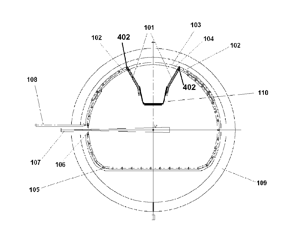
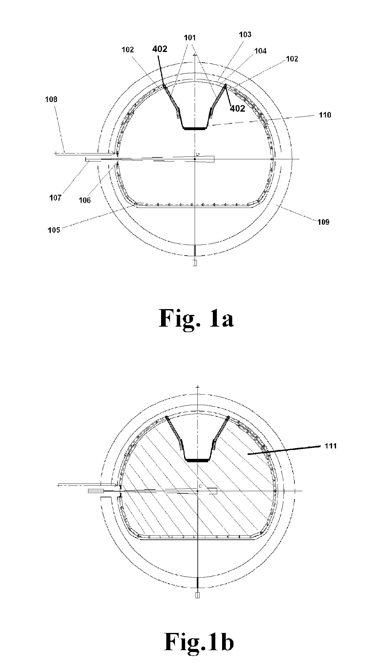
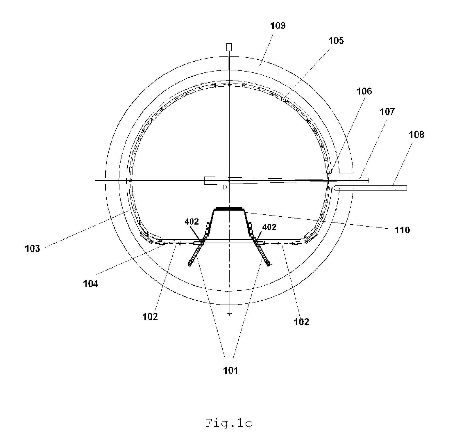
[0048]In particular, the present invention provides a particle therapy apparatus comprising a patient enclosure having a flat floor accessible to the practitioner without gaps or weaker parts close to the irradiation unit for any irradiation angle.

[0049]Furthermore, the present invention provides such a particle therapy apparatus able to comprise imaging devices.

[0050]Finally, the present invention provides an efficient particle therapy apparatus having a high safety level wherein minimal damages occur in case of blocking of a part of the device or apparatus.

[0051]A medical particle therapy apparatus is described referring to FIGS. 1 and 2. It...


PUM


Abstract

The present invention relates to an irradiation unit for emitting a particle beam, a gantry including the irradiation unit, a squirrel cage structure located within and supported by the gantry, a frame arranged so as to be motionless, a moving floor including a plurality of elongated members forming a primary caterpillar, two moving floor guide units having a truncated circle shape, facing each other, attached to said squirrel cage structure and the motionless frame, respectively. Each of the two moving floor guide units includes at least a first rail, said the primary caterpillar being slidably arranged on the first rail. Each moving floor guide unit includes at least a second rail having a truncated circle shape and the moving floor includes at least one secondary caterpillar including elongated members flexibly connected to each other.

Description

CROSS REFERENCE TO RELATED APPLICATIONS[0001]This application is a national phase application of International Application No. PCT / EP2009 / 067808, filed Dec. 22, 2009, designating the United States and claiming priority to European Patent Application No. 08022552.7, filed Dec. 31, 2008, and European Patent Application No. 09161605.2, filed May 29, 2009, all of which are incorporated by reference herein in their entirety.TECHNICAL FIELD[0002]The present invention is related to a medical apparatus for particle therapy wherein an irradiation unit is able to move inside a patient enclosure together with an imaging device.STATE OF THE ART[0003]Conventional cancer therapy uses high energetic photons like X-rays or gamma rays to destroy tumour cells. The main drawback of that method is that healthy cells surrounding tumour cells are irradiated in the same time, damaging these healthy cells which may cause atrophy or several secondary effects, such as the release of secondary tumours. Moreov...

Claims


Application Information

Patent Timeline
Patent Type & Authority Patents(United States)
IPC IPC(8): A61N5/10A61B6/04
CPCA61N5/1081A61N2005/1087A61N2005/1061
Inventor HAVELANGE, YORICKDE NEUTER, SEBASTIENPIRET, VINCENTBLEECKX, BERNARD
Owner ION BEAM APPL
Why Eureka
Try Eureka