
Methods and apparatus for camera calibration based on multiview image geometry

Active Publication Date: 2013-02-05
ADOBE INC
View PDF2 Cites 80 Cited by
  • Summary
  • Abstract
  • Description
  • Claims
  • Application Information

AI Technical Summary

Benefits of technology

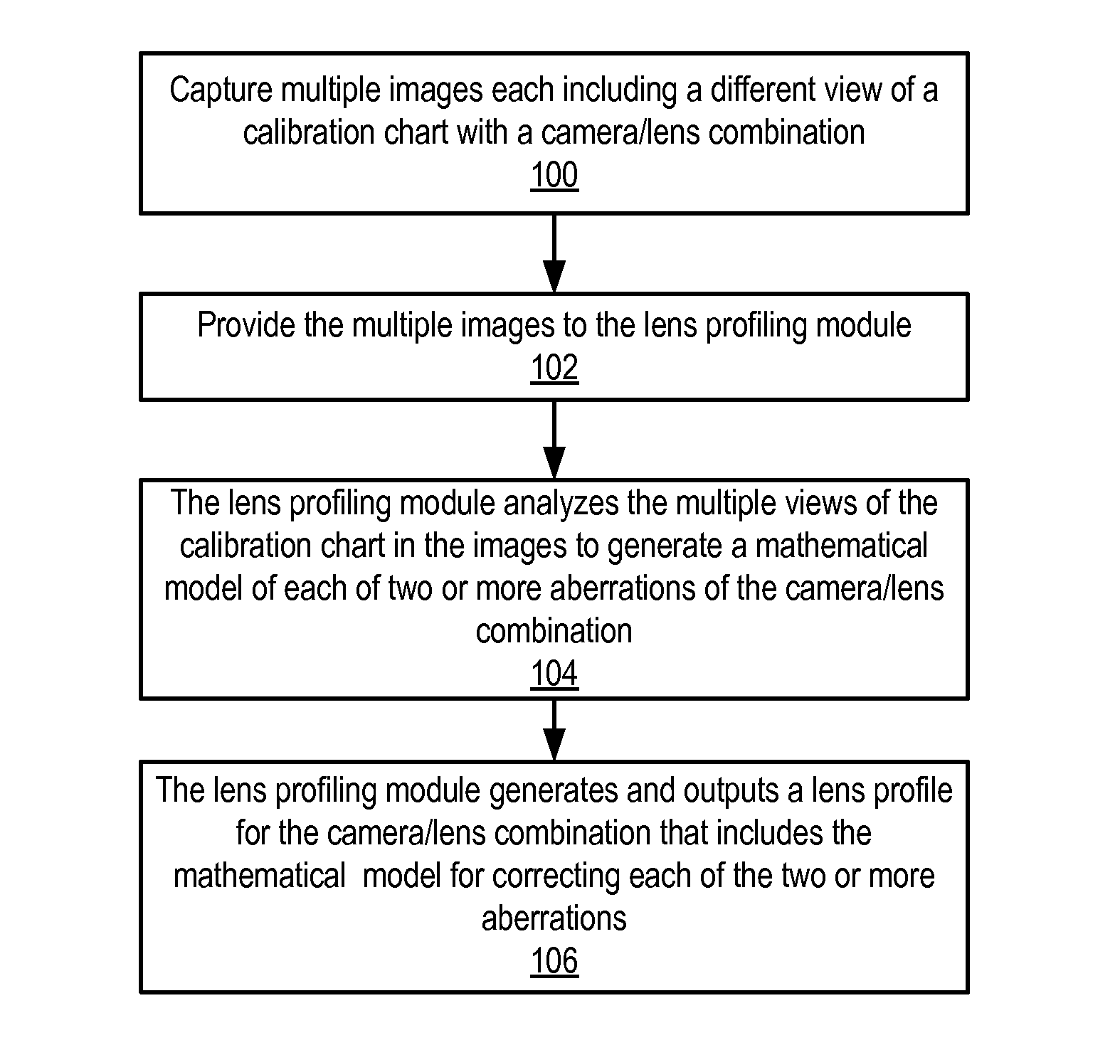
The patent describes a way to calibrate a camera by using multiple images of a chart taken from different angles. This approach makes it simpler and faster compared to traditional methods, and reduces the workload for users. The system can also suggest different models for correcting different kinds of aberrations based on the captured images. The user can choose the level of detail in the models, and the system will try different models to find the best one. Overall, this makes it easier and faster to calibrate cameras and produce high-quality images.

Problems solved by technology

However, in real world cameras, the camera lens typically involves design compromises and imperfections that may introduce lens aberrations in the captured image.
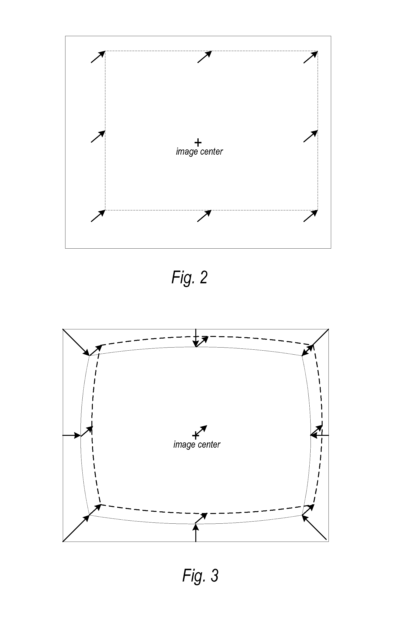
Tangential distortion may, for example, be present in a captured image as a result of imperfect alignment of lens elements or other manufacturing defects in a compound lens.
Conventional camera calibration methods thus typically require stringent studio setup and different setups for modeling different lens aberrations, making these methods difficult if not impossible for the typical photographer to attempt, and difficult and time-consuming even for professional photographers and photographic studios that have the facilities and skills necessary to attempt camera calibration.
In addition, these conventional camera calibration methods are difficult if not impossible to apply to some types of lenses.
This significantly relaxes the camera calibration setup when compared to conventional methods, simplifies the workflow for producing lens profiles when compared to conventional methods, and reduces the work of users who want to produce a complete lens profile when compared to conventional methods.

Method used


Image

  • Methods and apparatus for camera calibration based on multiview image geometry
  • Methods and apparatus for camera calibration based on multiview image geometry
  • Methods and apparatus for camera calibration based on multiview image geometry

Examples


example camera

Model

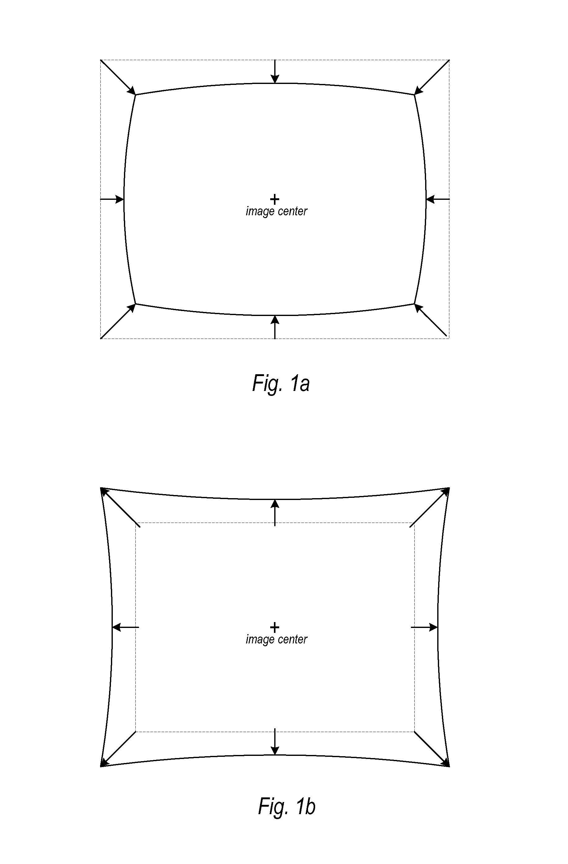
[0106]The following describes an example camera model that may be used in some embodiments of the lens profiling module, and is not intended to be limiting. The example camera model characterizes the most common form of lens aberrations, namely the geometric distortion (both radial and tangential distortions), the lateral chromatic aberration and the radial light falloff from the principal point (the vignetting), for various lens types including, but not limited to, rectilinear, wide-angle, and fisheye lenses. Note that, in some embodiments, other types of aberrations may be characterized in the camera model.

Principal Point

[0107]The principal point may be defined as the location of an image on an image plane formed by the direct optical axial ray passing through the perspective center of the lens. In some embodiments, the principal point may be fixed at the image center. In other embodiments, the location of the principal point may be estimated during model estimation. Some emb...


PUM


Abstract

Methods and apparatus for camera calibration based on multiview image geometry. A lens profiling module may estimate two or more mathematical models for correcting aberrations in images in a single pass from a set of calibration images captured with a camera / lens combination. For example, the module may estimate the lens aberrations of geometric distortion, lateral chromatic aberration, and vignette models in a single pass. The module may determine point correspondences, 3D transformations, and camera intrinsics for views of calibration charts captured in the images. The module estimates the mathematical models for the two or more types of aberrations from the information determined from the views of the calibration charts. The module may automatically determine an optimal model complexity when estimating the mathematical models. The estimated models may be written or appended to a lens profile for the camera / lens combination used to captured the calibration images.

Description

BACKGROUNDDescription of the Related Art[0001]Cameras are light capturing devices. The light begins as rays emanating from some source, such as the sun, and travels through space until striking some object. When that light reaches the object, much spectrum of the light is absorbed, and what is not absorbed is reflected. Some of this reflected light makes its way through the optics of the camera and is collected by the camera sensor (or film) at the image plane. The geometric configuration of the passage of a bundle of light rays from the object through the lens(es) to the image plane can be described mathematically by a parametric model, which may be referred to as the camera model.[0002]The pinhole camera model is a simplistic model in which the bundle of light rays would pass from the object to the image plane through a single perspective center to form a sharp image on the plane of focus according to the fundamental physical laws of the ray optics. In this ideal model, there is n...

Claims


Application Information

Patent Timeline
IPC IPC(8): H04N17/00
CPCH04N17/002
Inventor CHEN, SIMONJIN, HAILINCHIEN, JEN-CHANGOLDMAN, DANIEL R.
Owner ADOBE INC
Learn More