Steam generator of steam oven

a technology of steam oven and steam generator, which is applied in the direction of steam generation using steam absorption, combustion air/fuel air treatment, and container discharge from pressure vessels, etc. it can solve the problems of increased manufacturing costs, reduced workability, and limit the size of the inner space of the cooking chamber, so as to simplify the configuration of the device and facilitate cleaning and washing

Active Publication Date: 2013-02-05
LG ELECTRONICS INC
View PDF38 Cites 32 Cited by
  • Summary
  • Abstract
  • Description
  • Claims
  • Application Information

AI Technical Summary

Benefits of technology

[0011]Therefore, the present invention has been made in view of the above problems, and it is an object of the present invention to provide a steam generator of a steam oven, which can simplify the configuration of a device required to generate steam, and is detachably attached to a cabinet to assure easy cleaning and washing thereof.
[0012]It is another object of the present invention to provide a steam generator of a steam oven, which can more efficiently and rapidly generate steam by an improved water heating manner using a heater.
[0013]It is yet another object of the present invention to provide a steam generator of a steam oven, which can allow a steam discharge hole thereof to be automatically opened or closed when the steam generator is attached to or detached from a cabinet of the steam oven.

Problems solved by technology

The complicated configuration of the steam generating device causes not only a degradation in workability, but also increased manufacturing costs, and inevitably has a limit in the size of an inner space of the cooking chamber.
Moreover, the above described configuration of the steam generating device exhibits a complex coupling relationship of assembling elements, which makes it difficult for a consumer to disassemble the steam generating device by oneself.
Therefore, the steam generating device has a difficulty in cleaning and washing.
Also, when using the steam generating device for a long time, minerals (calcareous) contained in water are precipitated as scale, providing the steam generator with poor heating performance and unsanitary condition.

Method used


Image

  • Steam generator of steam oven
  • Steam generator of steam oven
  • Steam generator of steam oven

Examples


first embodiment

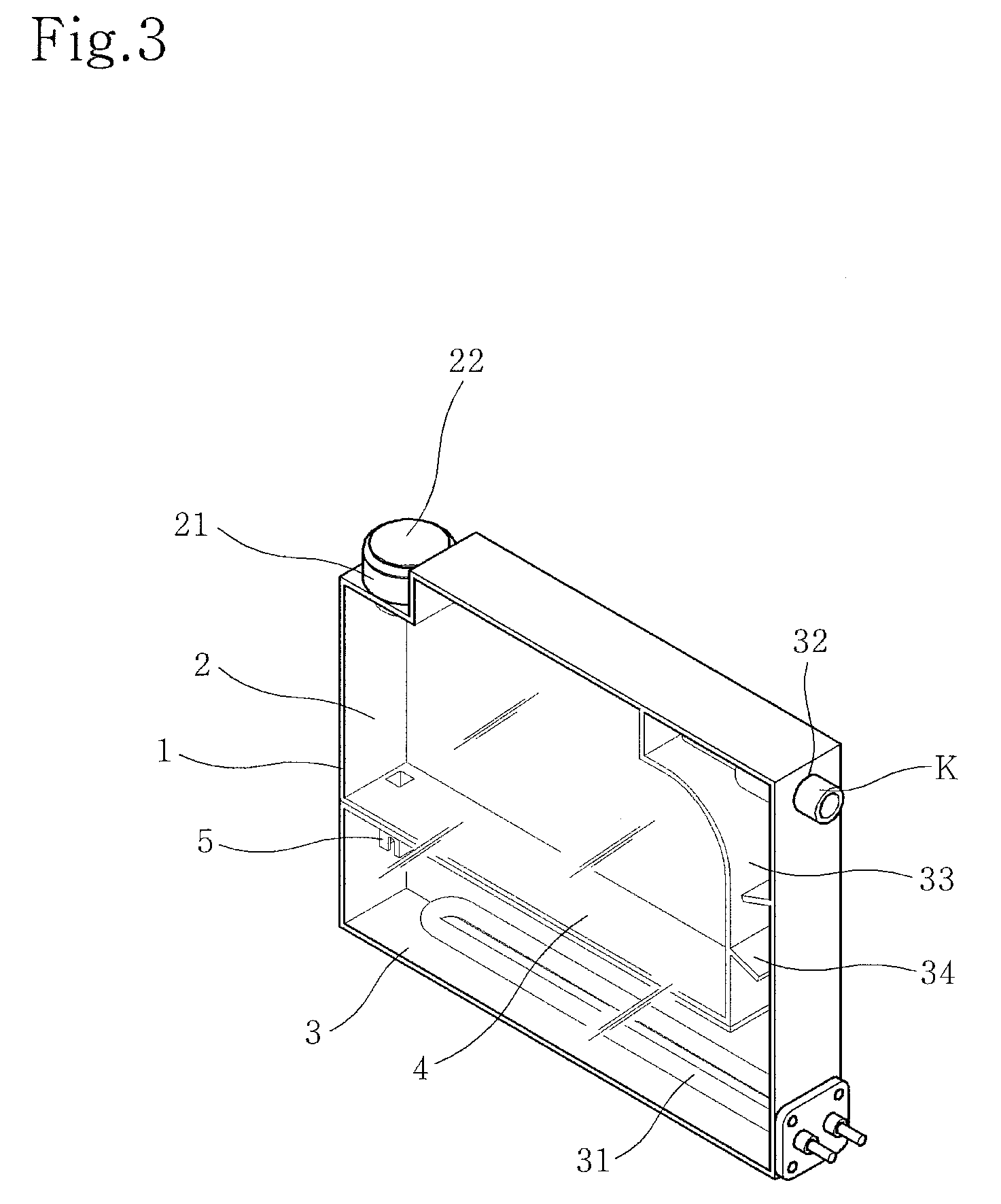
[0035]FIGS. 3 to 10 illustrate a steam generator according to the present invention. More particularly, FIG. 3 is a perspective view illustrating the overall configuration of the steam generator, FIG. 4 is a longitudinal sectional view of FIG. 3, and FIG. 5 is an enlarged sectional view of the portion “B” in FIG. 4.

[0036]As shown, the steam generator according to the present invention includes a rectangular upright body 1 having a water pouring hole 21 and a steam discharge hole 32. The inner space of the upright body 1 is divided into upper and lower compartments by a partition 4, the upper compartment serving as a water supply compartment 2 and the lower compartment serving as a boiler compartment 3. A water supply passage 5 is provided between the water supply compartment 2 and the boiler compartment 3, to allow water stored in the water supply compartment 2 to be introduced into the boiler compartment 3 through the water supply passage 5.

[0037]The water pouring hole 21 and the s...

second embodiment

[0060]FIGS. 11 and 12 illustrate a steam generator according to the present invention. More particularly, FIG. 11 is a perspective view illustrating the overall configuration of the steam generator, and FIG. 12 is a longitudinal sectional view of FIG. 11.

[0061]The most important difference between the present embodiment and the previously described first embodiment is positions of the water pouring hole 21 provided with the plug 22 and the steam discharge hole 32.

[0062]Differently from the first embodiment of the present invention in which the water pouring hole 21 is located at the opposite side of the steam discharge hole 32, in the second embodiment of the present invention, the water pouring hole 21 is located at the same side as the steam discharge hole 32. When providing the water pouring hole 21 at the opposite side of the steam discharge hole 32, water can be supplemented through the water pouring hole 21 without completely separating the upright body 1 of the steam generato...

third embodiment

[0065]FIGS. 13 to 15 illustrate a steam generator according to the present invention. More particularly, FIG. 13 is a perspective view illustrating the overall configuration of the steam generator, FIG. 14 is a longitudinal sectional view of FIG. 13, and FIG. 15 is a perspective view illustrating the steam generator installed on the top of the cabinet.

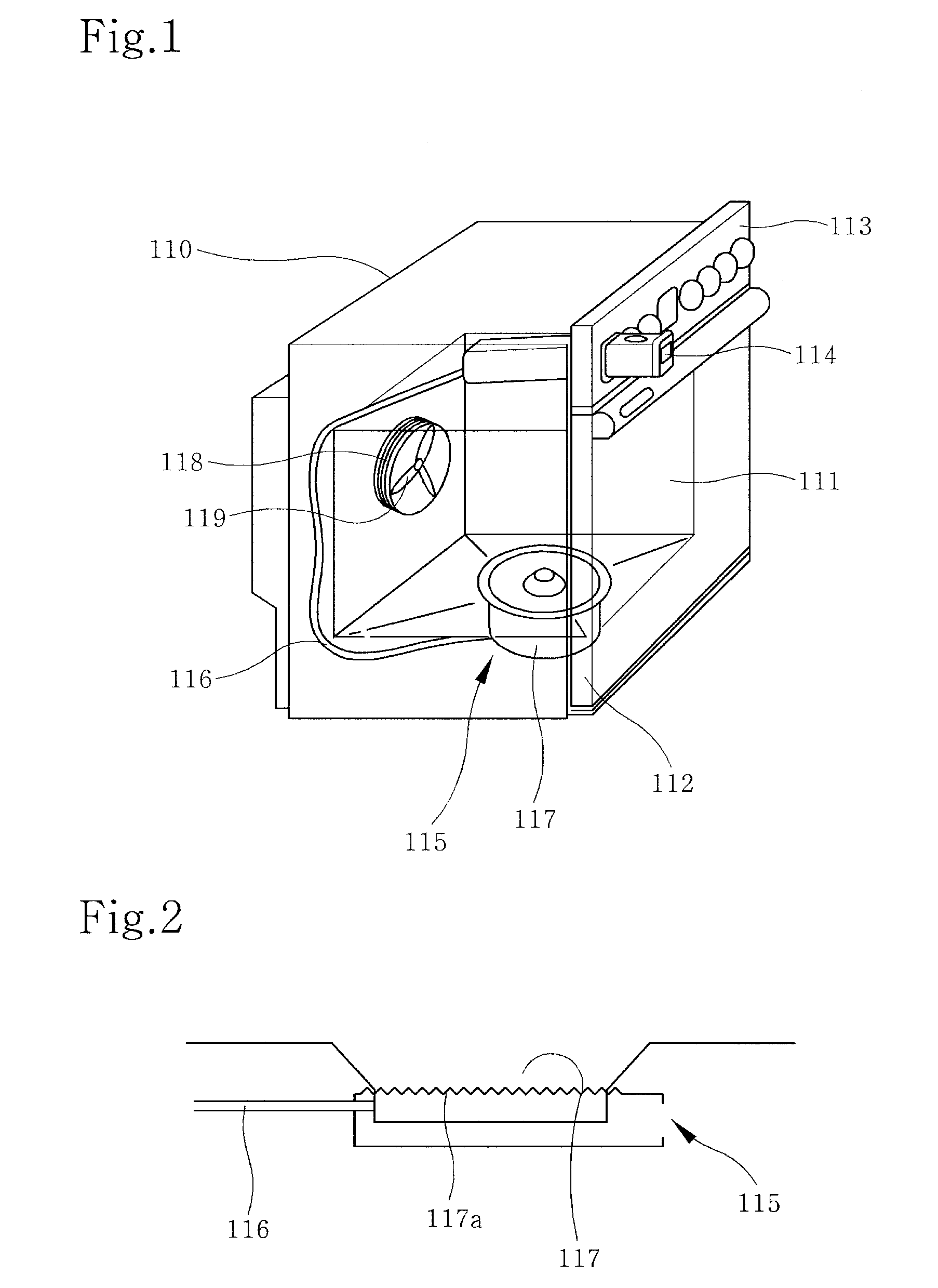
[0066]The present embodiment, as shown in FIG. 15, has a feature in that the steam generator is mounted on the top of the cabinet 110. In this case, the body of the steam generator is configured to be laid horizontally on the cabinet so as not to require a wide installation area therefor. In this case, the fixing bracket 8 is mounted on the top of the cabinet 110 to support and fix the body of the steam generator.

[0067]Similar to the above described first and second embodiments of the present invention, the technical principal of Torricelli's Experiment also can be applied to the steam generator according to the third embodiment of the...


PUM

PropertyMeasurementUnit
lengthaaaaaaaaaa
heightaaaaaaaaaa
external pressureaaaaaaaaaa

Abstract

Disclosed is a steam oven to cook food in a cooking chamber by use of steam. More particularly, disclosed is a steam generator of a steam oven, which can simplify the configuration of a device required to generate steam and is detachably attached to a cabinet to assure easy cleaning and washing thereof. The steam generator includes a single body having an inner space divided into a water supply compartment and a boiler compartment by a partition, the water supply compartment having a water pouring hole, and the boiler compartment having a heater and a steam discharge hole. Also, a water supply passage is defined between the water supply compartment and the boiler compartment. This configuration has the effects of achieving improved workability and reduced manufacturing costs of the steam generator and also, of overcoming a limit in the inner volume of a cooking chamber of the steam oven.

Description

BACKGROUND OF THE INVENTION[0001]1. Field of the Invention[0002]The present invention relates to a steam oven to cook food in a cooking chamber by use of steam, and more particularly, to a steam generator of a steam oven, which can simplify the configuration of a device required to generate steam and is detachably attached to a cabinet to assure easy cleaning and washing thereof.[0003]2. Description of the Related Art[0004]FIG. 1 is a perspective view illustrating the overall configuration of a conventional steam oven. The steam oven includes a cabinet 110 defining a cooking chamber 111 therein, a door 112 to open or close the cooking chamber 111, and a control panel 113 provided at an upper location of a front surface of the cabinet 110, the control panel 113 having a variety of operating switches and a display to provide information.[0005]The steam oven further includes a steam generating device received in the cooking chamber 111. The steam generating device includes a water inje...

Claims


Application Information

Patent Timeline
Patent Type & Authority Patents(United States)
IPC IPC(8): F24H1/18
CPCF24C15/327A21B3/04A47J27/16F24C7/006F24C13/00
Inventor LEE, YONG-WOOYANG, JAE-KYUNGKIM, YANG-KYEONGPARK, SUNG-IL
Owner LG ELECTRONICS INC
Why Eureka
Try Eureka