Method and template for producing a tensile test coupon

a coupon and tensile technology, applied in the direction of tensile/compressive force of materials, instruments, mechanical means, etc., can solve the problems of high force required to bend the strap, destructive field-testing methods have been devised, and the instrumentation and apparatus are not suited for field use, etc. to achieve the effect of convenient site location

Active Publication Date: 2013-02-12
MCELROY MFG
View PDF6 Cites 6 Cited by
  • Summary
  • Abstract
  • Description
  • Claims
  • Application Information

AI Technical Summary

Benefits of technology

[0011]The template for use in producing a tensile test coupon from a plastic pipe has a plate contoured for stable abutment on the outer surface of the pipe. For example, the contour may be a V-groove aligning the longitudinal axis of the plate with the longitudinal axis of the pipe. An array of holes through the plate defines a straight-line-connectable point-to-point pattern for the coupon. At least two additional holes through the plate and within the pattern of the coupon are oriented to facilitate application of test tensile force to the extracted coupon at the narrowest cross-section of the coupon. The holes of the coupon-defining array may be arranged for symmetrical orientation in relation to a pair of intersecting axes, one axis being tangential to and the other axis being longitudinal along, the outer surface of the pipe when the plate is in stable abutment on the pipe. The symmetrical orientation of the array enables production of a symmetrical coupon. The at least two additional holes may be arranged for symmetrical orientation straddling the tangential axis and along the longitudinal axis. The symmetrical orientation of these holes, in cooperation with the symmetry of the coupon, allows the test tensile force to be symmetrically applied to the coupon. The plate is provided with a relief to receive beads formed on the outer surface of the pipe by fusion of the pipe along its plane of fusion interface. The tangential axis lies in the plane of interface so the plate can be in stable abutment on the pipe even though the outer diameter of the joint at the beads is greater than the outer diameter of the pipe. The holes of the coupon-defining array and the additional symmetrical holes may each be fitted with a hardened drill bushing.
[0014]An array of holes through the plate defines a straight-line-connectable bow-tie-like pattern for the coupon. The holes of the coupon-defining array may be arranged symmetrically in relation to a pair of intersecting axes, one of which will be tangential to and the other of which will be longitudinal along the outer surface of the pipe when the plate is in stable abutment against the pipe. The symmetrical orientation of the array enables production of a symmetrical coupon. The bow-tie-knot portion of coupon pattern may be defined by two or four of the holes of the array.
[0015]At least two additional holes oriented within the pattern of the coupon and extending through the plate facilitate the locating of sites on the coupon at which tensile force can be applied to the coupon at the narrowest cross-section of the bow-tie-knot portion of the pattern. The additional holes may be symmetrically displaced from the tangential axis and lie on the longitudinal axis. The symmetrical orientation of these holes, in cooperation with the symmetry of the coupon, allows the test tensile force to be symmetrically applied to the coupon.

Problems solved by technology

Unfortunately, most of the tensile test methods now available require instrumentation and apparatus which are not suited for field use.
A few destructive field-testing methods have been devised for checking the mechanical performance of the fused joint during pipeline production.
The required length of the “bend back” strap may vary and, for greater pipe wall thicknesses, the forces required to bend the strap become high, containment in the case of failure becomes more difficult and the method becomes safety and cost prohibitive.
In addition, the levels of stress imposed upon the fused joint are heavily dependent on uncontrolled or unknown factors such as the bend radius and the types of tooling used to bend the strap.
These variables result in uncertainty as to the significance of any passing grade resulting from this test.
Furthermore, for larger pipe diameters which require longer straps of pipe for testing, the material cost for the strap of pipe required to apply an appropriate bend test load can be quite expensive.

Method used


Image

  • Method and template for producing a tensile test coupon
  • Method and template for producing a tensile test coupon
  • Method and template for producing a tensile test coupon

Examples


first embodiment

of the Template

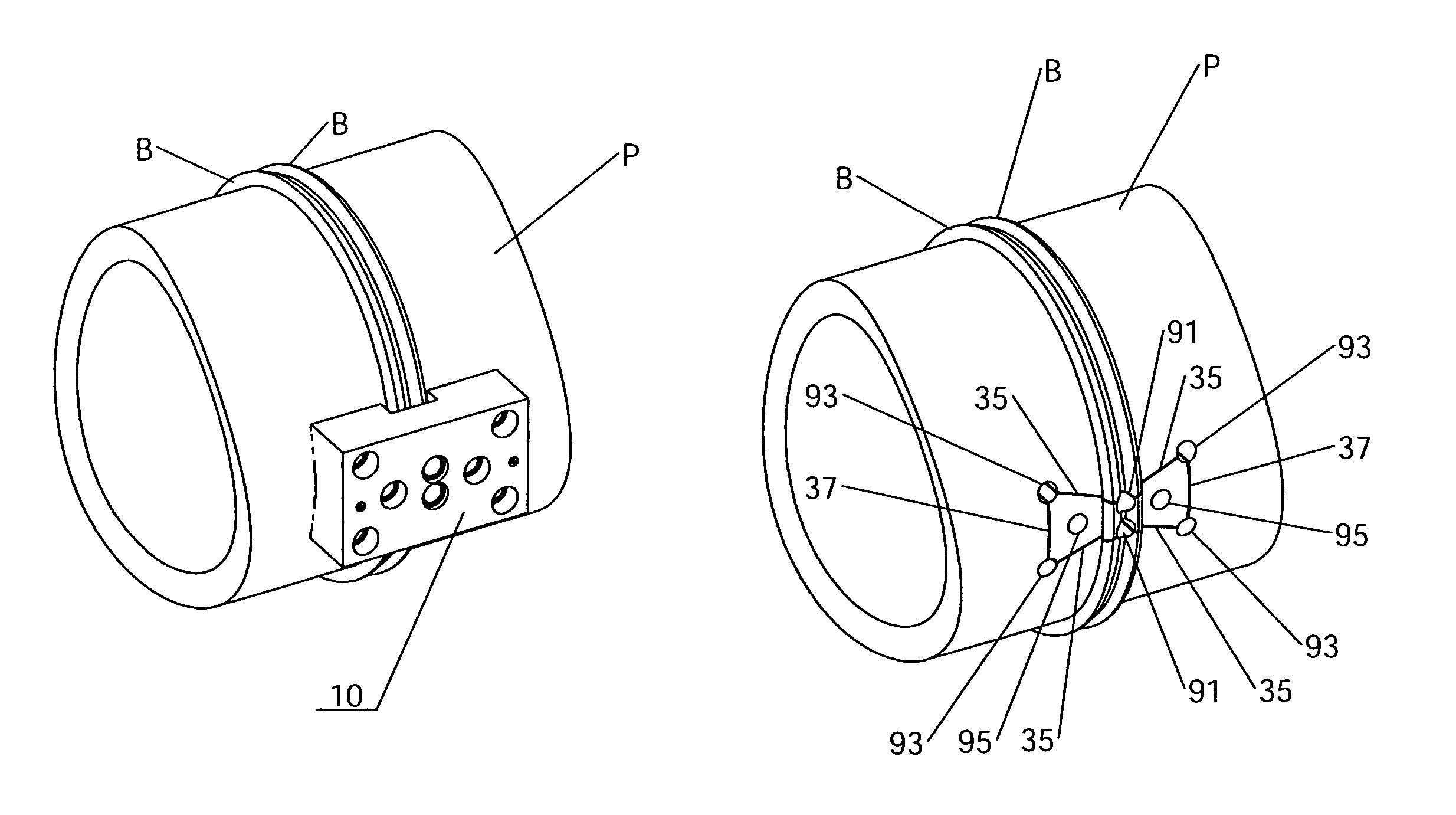
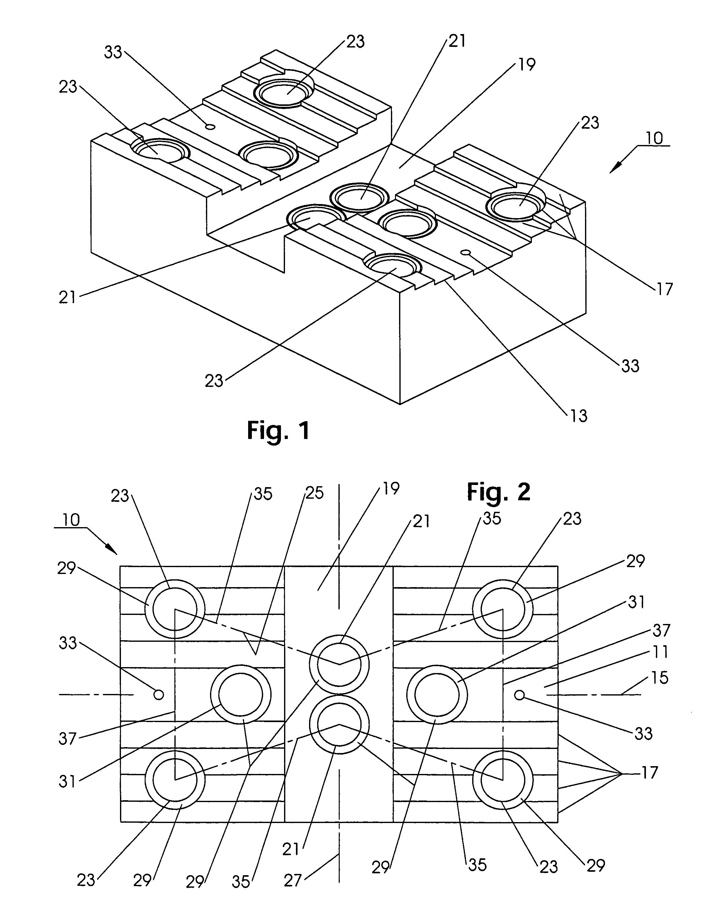
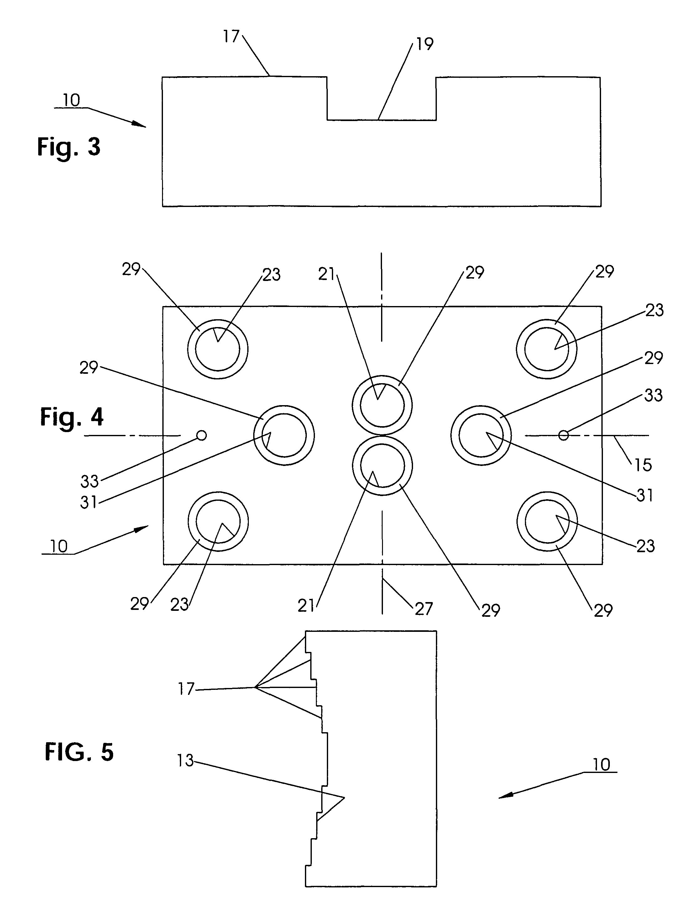
[0071]Turning to FIGS. 1-12, a screw-in-place, symmetric mount embodiment of a template 10 for producing a tensile test coupon 80, seen in FIGS. 13-17, from a plastic pipe P or a fused joint J of a plastic pipe P is illustrated. The template 10 is useful over a broad range of pipe diameters and compositions, but is particularly applicable for medium or high density polyethylene pipes.

[0072]The template 10 is formed using a relatively thick plate of material such as commercially available aluminum or steel suited for machining. The template 10 has a base 11 which, in using the template 10, will be abutted against the outer surface of the pipe P. The contour of the base 11 can take many shapes so long as the template 10 is stable in its alignment when held against a pipe P.

[0073]As shown, the base 11 has a V-groove 13 which, in cross-section, is transverse to the longitudinal axis 15 of the template 10. Thus, the pipe and template longitudinal axes L and 15 will be para...

second embodiment

of the Template

[0078]The first embodiment template 10 used screws to fix the template securely to the outer surface of the pipe to be tested. This method works well where pipes are fairly structurally stable, as when pipes are heavy wall and / or of large diameter. This method works adequately to stabilize the template to the degree necessary to produce a precisely drilled coupon. Smaller pipes lack the necessary rigidity and tend to displace out of the way of the drill bit as the holes are being drilled, possibly leading to distorted hole arrays in the coupons so that the drilled holes are not precisely aligned as is desired. The U-bolt arrangement envelopes the pipe being tested and draws it into firm contact with the stabilizing contour of the template. The U-bolts are threaded on their ends and threaded nuts are used to tighten them against the pipe, drawing it into firm contact with the template. These U-bolts also help the pipe to maintain its shape while it is being drilled.

[00...

third embodiment

of the Template

[0097]Looking at FIGS. 29-33, a U-bolt, asymmetric mount embodiment of the template 310 for producing a tensile test coupon 380, best seen in FIGS. 40-45, from a plastic-pipe P or a fused joint J of a plastic pipe P is illustrated. The template 310 is useful over a broad range of pipe diameters and compositions, but is particularly applicable for smaller diameter medium or high density polyethylene pipes.

[0098]A coupon hole-array profile with a single reduced section lying in the plane of the interface of two fused pipes has to be interpreted in order to provide a meaningful estimation as to the quality of the joint. While a tensile coupon prepared from a single stick of good quality base pipe will always fail in the reduced area in a ductile fashion, a tensile coupon prepared at a pipe joint presents multiple possibilities. The very worst joints will break abruptly under tensile load, leaving a smooth parting face, and showing no evidence of cohesion between the pipe...


PUM

PropertyMeasurementUnit
tensile testaaaaaaaaaa
tensile forceaaaaaaaaaa
tensile strengthaaaaaaaaaa

Abstract

A method and template enable the testing of fusion joints of plastic pipes to be conducted by a single operator in the field at the welding site by the efficient and precise extraction from the joints to be tested of a number of high quality tensile coupons. The coupons are tested to failure in a field-suitable, well controlled, self contained, tensile testing apparatus. A narrowing bow-tie-like pattern of the coupon ensures that the failure of the coupon in the tensile test will occur at the narrowest section of the coupon. The template can be visually aligned with the joint to ensure that it is the joint that will be tested.

Description

BACKGROUND OF THE INVENTION[0001]This invention relates generally to the quality testing of heat-fused plastic pipe joints and more particularly concerns a method and template for producing a coupon which can be used to test the properties, such as the tensile strength and ductility, of a pipe joint as the pipe is being laid in the field.[0002]Plastic pipes, such as pipes made of medium or high density polyethylene, can be joined by a variety of methods, a common joining method being butt-fusion. The procedure for this method involves inserting pipes to be fused into a specially designed fusion machine which aligns and holds the pipes axially with respect to each other and with pipe ends adjacent to each other, clamping the pipes securely in the jaws of the fusion machine, cleaning of the pipe ends to be fused, facing the pipe ends to ensure clean and square pipe ends with material exposed that is suitable for heat fusion, heating the pipe ends for an appropriate amount of time, and...

Claims


Application Information

Patent Timeline
Patent Type & Authority Patents(United States)
IPC IPC(8): G01B3/14
CPCG01N3/08B29C65/8215B29C66/1142B29C66/5221B29C66/73921G01N2203/0298B29C66/71B29C65/02B29K2023/065B29K2023/0641
Inventor LAWRENCE, JASON A.PERRAULT, JAMES R.O'CONNELL, BRIAN
Owner MCELROY MFG
Why Eureka
Try Eureka