Flywheel device

a technology of flywheel and mass ring, which is applied in the direction of spring/damper, rotational vibration suppression, vibration suppression adjustment, etc., can solve the problems of reducing the mass productivities of components, disadvantageous in terms of costs, and reducing production costs, so as to facilitate the increase of the mass of the mass ring

a technology of flywheel and mass ring, which is applied in the direction of spring/damper, rotational vibration suppression, vibration suppression adjustment, etc., can solve the problems of reducing the mass productivities of components, disadvantageous in terms of costs, and reducing production costs, so as to facilitate the increase of the mass of the mass ring

US8371948B2Inactive Publication Date: 2013-02-12YUTAKA GIKEN CO LTD

Image

  • Flywheel device
  • Flywheel device
  • Flywheel device

Examples


Embodiment Construction

[0023]An embodiment of the present invention will be described below based on the attached drawings.

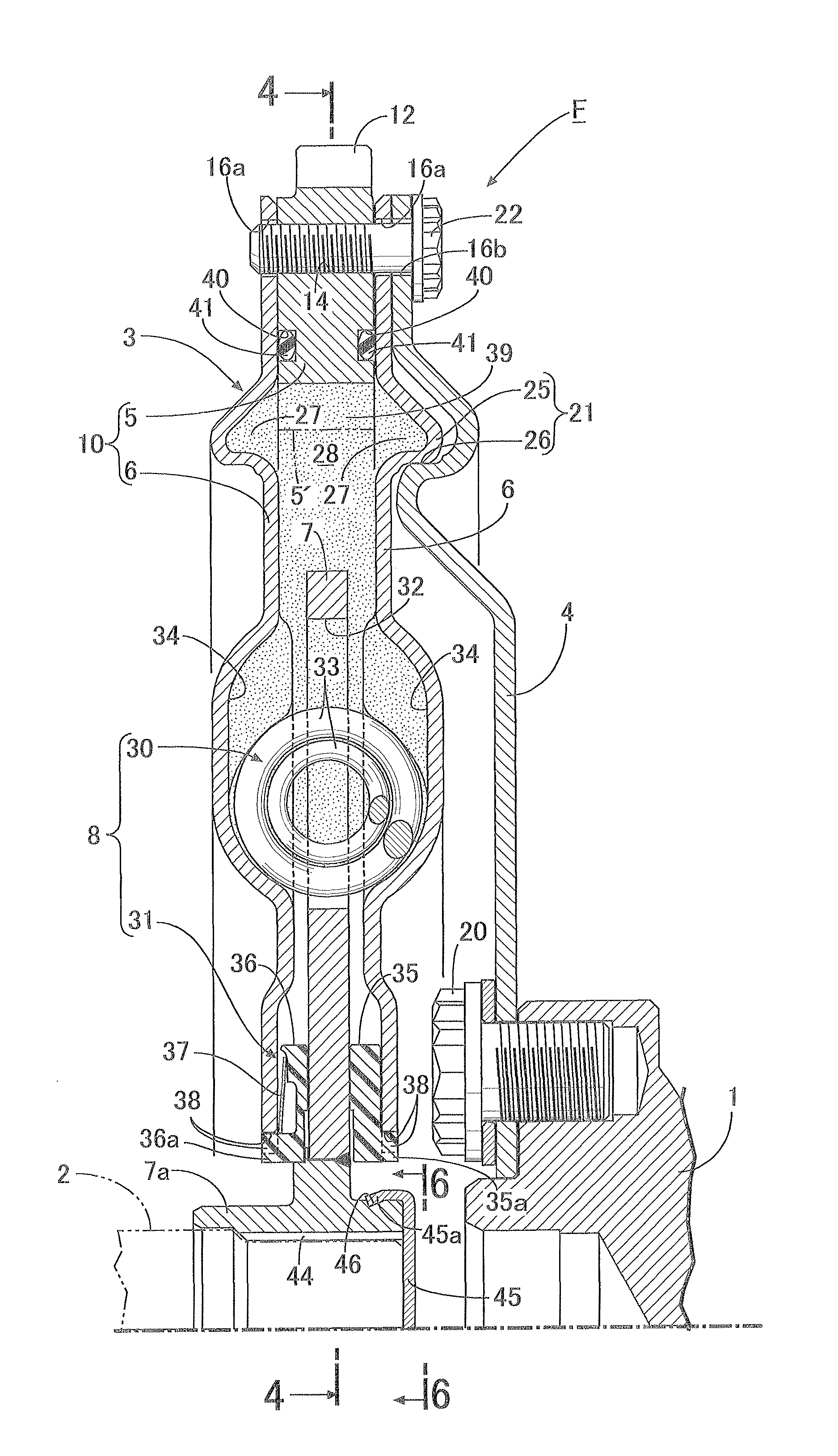
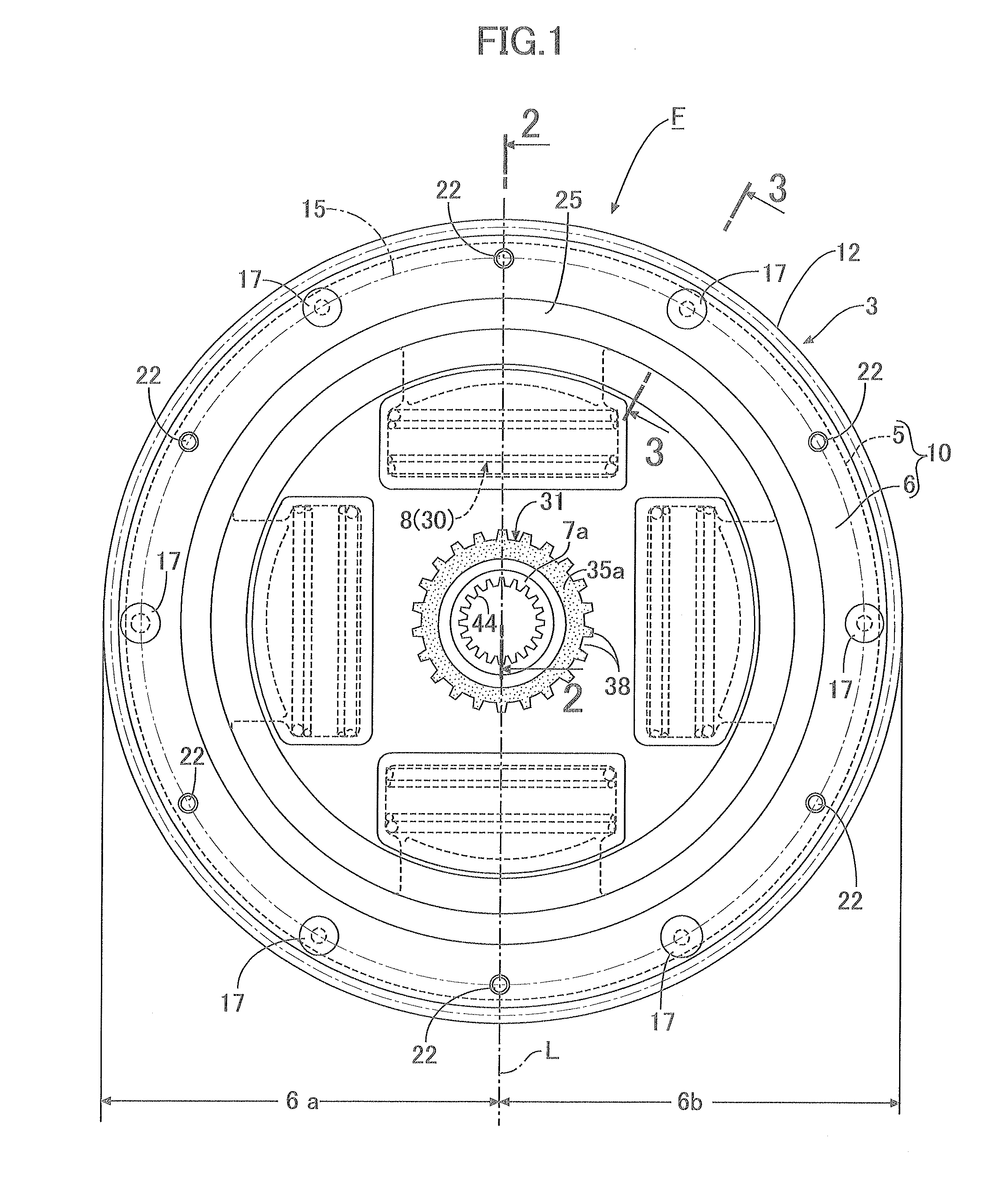
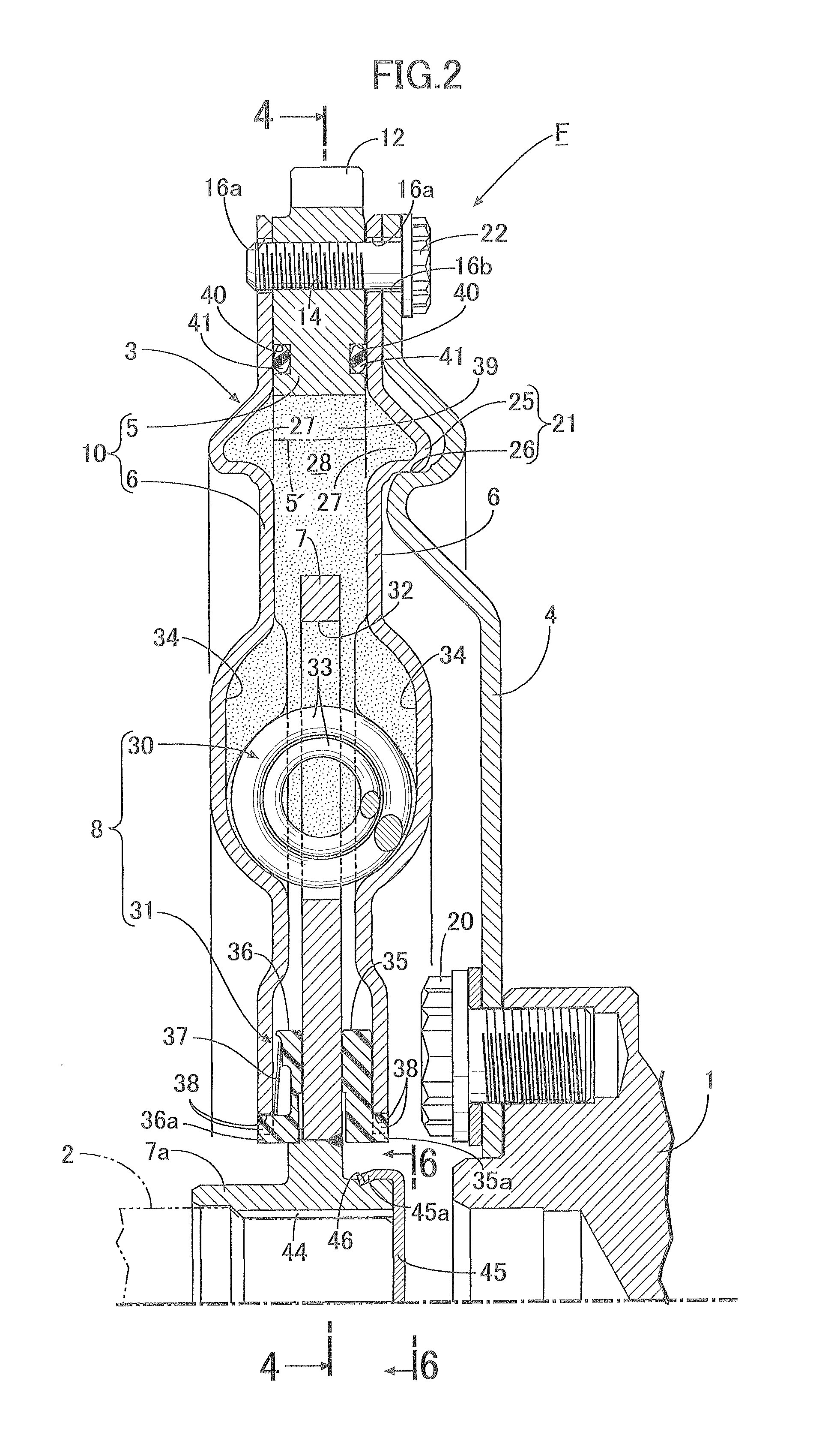
[0024]In FIGS. 1 to 3 and 7, power from a crankshaft 1 of an engine is transmitted through a flywheel device F of the present invention to an output shaft 2 continuing to a clutch or a transmission. The flywheel device F includes a flywheel assembly 3 and a drive plate 4 connecting the flywheel assembly 3 to the crankshaft 1.

[0025]The flywheel assembly 3 includes a mass ring 5, a pair of holder plates 6, 6, a driven plate 7, and a torque damper 8. The holder plates 6, 6 have their outer peripheral portions connected to the mass ring 5 with the mass ring 5 sandwiched therebetween. The driven plate 7 includes an output hub 7a disposed coaxially with the mass ring 5 and is disposed between the holder plates 6, 6 rotatably relative to holder plates 6, 6. The torque damper 8 is interposed between the holder plates 6, 6 and the driven plate 7. In addition, the mass ring 5 and both the holde...


PUM


Abstract

A flywheel device includes a mass-side rotor including a mass ring and a pair of holder plates connected to both sides of the mass ring. The mass-side rotor is connected to a crankshaft with a drive plate therebetween. Between the mass-side rotor and the drive plate, a positioning apparatus for positioning those coaxially with each other is provided. The positioning apparatus includes: an annular positioning protrusion which is press formed in at least one of the pair of holder plates to project laterally outward therefrom, and which is disposed coaxially with the mass-side rotor; and a positioning recessed portion which is press formed in the drive plate coaxially with the crankshaft, and which is fitted to the positioning protrusion. Accordingly, it is possible to enable coaxial positioning of the mass-side rotor and the drive plate without performing burdensome machining on the mass ring for forming a positioning apparatus.

Description

BACKGROUND OF THE INVENTION[0001]1. Field of the Invention[0002]The present invention relates to an improvement of a flywheel device, in which a flywheel assembly includes: a mass-side rotor including a mass ring and a pair of holder plates having outer peripheral portions connected to the mass ring with the mass ring sandwiched therebetween; a driven plate which includes an output hub disposed coaxially with the mass ring and which is disposed between the holder plates rotatably relative to the holder plates; and a torque damper interposed between the holder plates and the driven plate, the mass-side rotor is connected to a crankshaft with a drive plate therebetween, and positioning means for positioning the mass-side rotor and the drive plate coaxially with each other is provided between the mass-side rotor and the drive plate.[0003]2. Description of the Related Art[0004]Such a flywheel device is already known, for example, as disclosed in Japanese Patent Application Laid-open No....

Claims


Application Information

Patent Timeline
12 Feb 2013
Publication
US8371948B2
IPC
F16F15/12; F16F15/167
CPC
F16F15/1203; F16F15/1207; F16F15/13164; F16F15/1315; Y10T74/2132
Inventors
USUI, ICHIRO; SAITO, HIROYUKI