Fiber laser substrate processing

a technology of fiber laser and substrate, applied in the direction of semiconductor/solid-state device testing/measurement, instruments, therapy, etc., can solve the problems of limiting the speed at which a substrate can be heated and the optimal use of new alternative light sources to meet new processing requirements, etc., to achieve rapid increase and decrease in illumination intensity

Active Publication Date: 2013-02-12
APPLIED MATERIALS INC
View PDF6 Cites 2 Cited by
  • Summary
  • Abstract
  • Description
  • Claims
  • Application Information

AI Technical Summary

Benefits of technology

[0005]Embodiments of the present invention pertain to substrate processing equipment and methods incorporating light sources which provide independent control of light pulse duration, shape and repetition rate. Embodiments further provide rapid increases and decreases in intensity of illumination.

Problems solved by technology

The rate with which the lamps 125 can be turned on and off is limited with typical heat lamps and results in limitations on how fast a substrate can be heated.
However these new alternative light sources are not optimal to satisfy new processing requirements that include time requirements for processing wafers that have been decreased to be between 50 nsec and 100 μs.

Method used


Image

  • Fiber laser substrate processing
  • Fiber laser substrate processing
  • Fiber laser substrate processing

Examples


Embodiment Construction

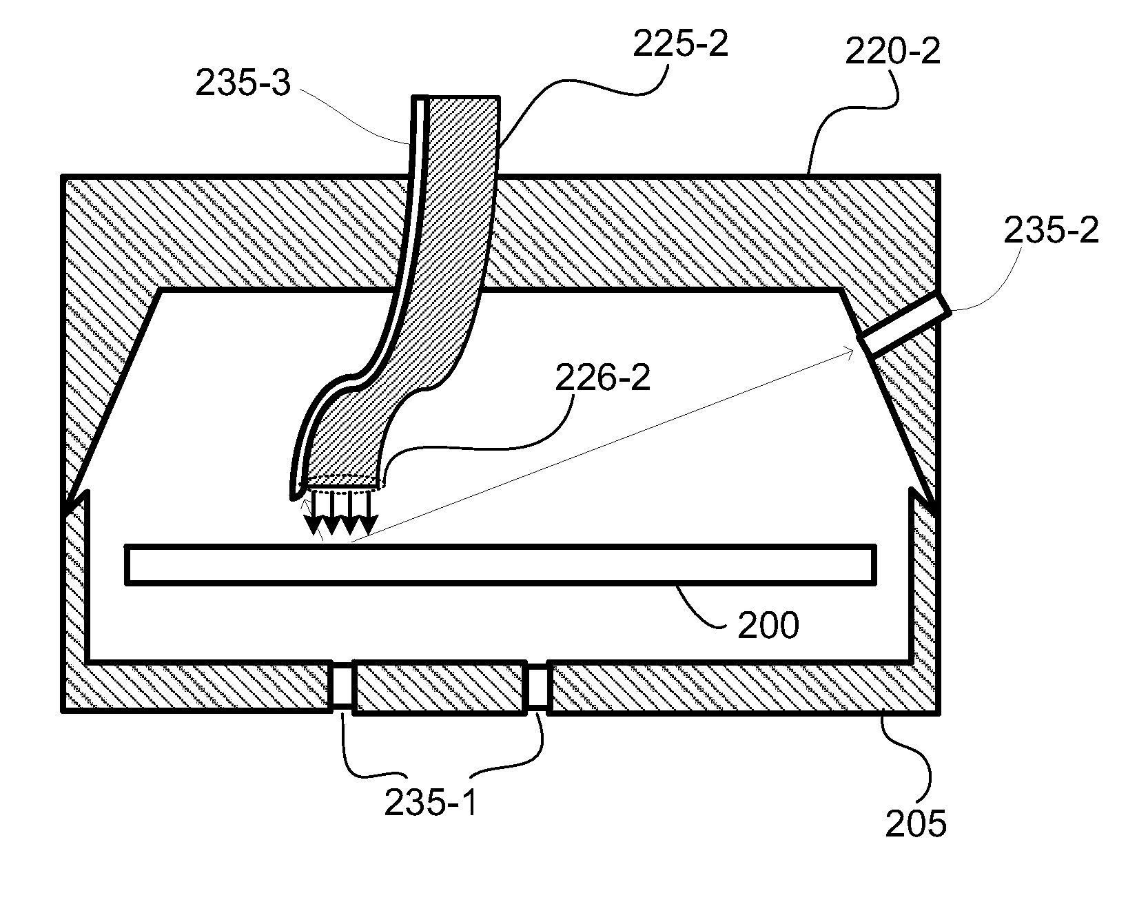
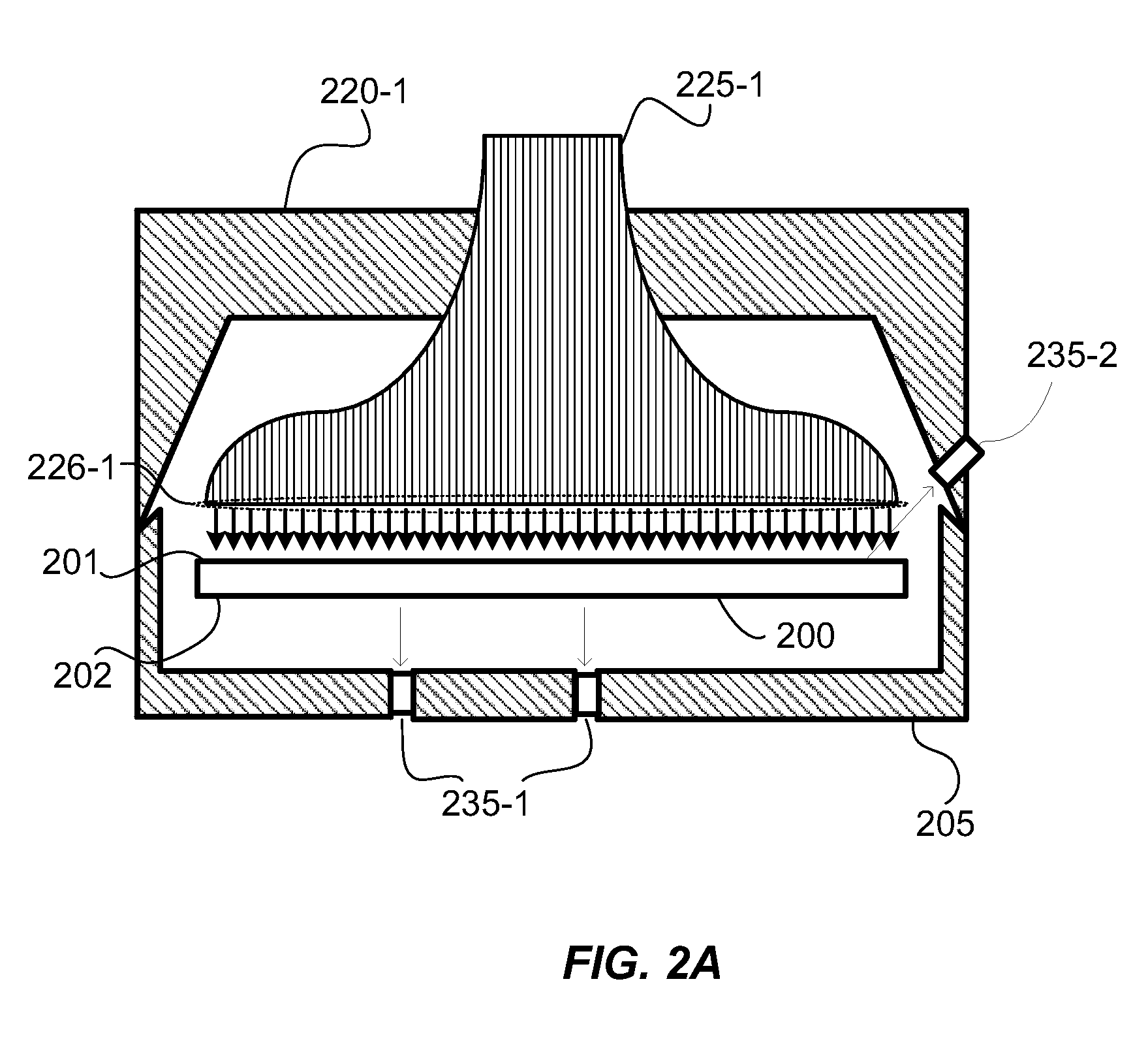
[0016]Embodiments of the present invention pertain to substrate processing equipment and methods incorporating light sources which provide independent control of light pulse duration, shape and repetition rate. Embodiments further provide rapid increases and decreases in intensity of illumination.

[0017]In a disclosed embodiment, fiber lasers are used to illuminate and heat the surface of a substrate to process the near surface region of the substrate. The processes include forming films, treating dopants and reordering the substrate itself. Fiber lasers can be used to create very intense optical pulses enabled by long lasing cavities which can be coiled to maintain a small tool footprint. The long narrow lasing cavities of fiber lasers can be cooled very efficiently further enabling a high optical intensity output. Continuous power from currently available fiber lasers exceed 1 kWatt which translates to very high peak powers depending on repetition rate, number of pulses, pulse shap...


PUM

PropertyMeasurementUnit
areaaaaaaaaaaa
temperaturesaaaaaaaaaa
wavelengthsaaaaaaaaaa

Abstract

Embodiments of the present invention pertain to substrate processing equipment and methods incorporating light sources which provide independent control of light pulse duration, shape and repetition rate. Embodiments further provide rapid increases and decreases in intensity of illumination.

Description

CROSS-REFERENCE TO RELATED APPLICATIONS[0001]This application claims the benefit of U.S. Provisional Application No. 61 / 171,011, filed Apr. 20, 2009, which is incorporated herein by reference in its entirety for all purposes.BACKGROUND OF THE INVENTION[0002]In some processes used in the semiconductor industry, it is desirable to heat a substrate rapidly to reduce the time it takes to process the substrate. Typically, rapid thermal processing systems utilize a high intensity light source to rapidly heat a substrate that is held within a processing chamber, sometimes under vacuum conditions. The high intensity light source, which may consist of an array of high intensity lamps, is located inside the chamber or outside of the chamber and adjacent to a transparent window through which the light passes into the chamber. Inside of the chamber the substrate is supported with very little physical contact (usually around the edge) so the substrate temperature can respond quickly to the incom...

Claims


Application Information

Patent Timeline
Patent Type & Authority Patents(United States)
IPC IPC(8): G01R31/26H01L21/66
CPCB23K26/0042B23K26/127B23K26/12B23K26/0604B23K26/0006B23K2103/56H01L21/324
Inventor MOFFATT, STEPHEN
Owner APPLIED MATERIALS INC
Why Eureka
Try Eureka