Wind turbine generator and motor

a technology of wind turbines and generators, applied in the direction of rotors, vessel construction, greenhouse gas reduction, etc., can solve the problems of low efficiency of turbines, device not maximizing the amount of power extracted from incident winds or fluid flows, and long blade length tends to limit the width

Active Publication Date: 2013-02-12
GRIGG CHARLES
View PDF22 Cites 11 Cited by
  • Summary
  • Abstract
  • Description
  • Claims
  • Application Information

AI Technical Summary

Benefits of technology

[0012]The invention introduces the use of turbine wings mounted on pivot shafts that are mounted in paired relationship and transversely mounted on a central drive shaft. The pivot shafts all rotate about the central drive shaft. Each pivot shaft enables its respective wings to rotate cyclically from a wind-engaging orientation (drive position) in which the wing presents a flat surface approximately transverse to the incident wind, to a minimum drag position (glide position) that enables the wing to rotate around the central drive shaft with minimum energy loss until it returns “into the wind” and repeats the cycle and rotates the pivot shaft and moves into drive position once again.
[0021]The wind turbine may be built to a size and conformation such that it is portable on a truck bed and easily relocatable to places where the wind is blowing. Thus seasonal wind changes can be exploited without requiring placement of the wind turbine in a fixed location.

Problems solved by technology

However, it is apparent that the frontal contact area of the turbine blades of one of these typical turbines is a very small fraction of the virtual disk surface swept by the blades in a complete rotation, which leads to the conclusion that a great amount of wind energy is passing through the swept area of the turbine without contacting a blade or contributing any useful work toward power generation.
Thus these turbines are necessarily low efficiency devices, when efficiency is calculated at a ratio of generated power to the wind power passing through the turbine's swept area.
In general, the long length of the blades tends to limit their width because of considerations of increased mass rotating, and increased lateral wind loads therefrom, at the top of the tower.
This device does not maximize the amount of power extracted from incident winds or fluid flows, and the torque it generates is not counterbalanced by any mechanical force other than the expedient of anchoring it to fixed points.
These forces are unbalanced and creates unbalanced intake and discharge flows.

Method used


Image

  • Wind turbine generator and motor
  • Wind turbine generator and motor
  • Wind turbine generator and motor

Examples


Embodiment Construction

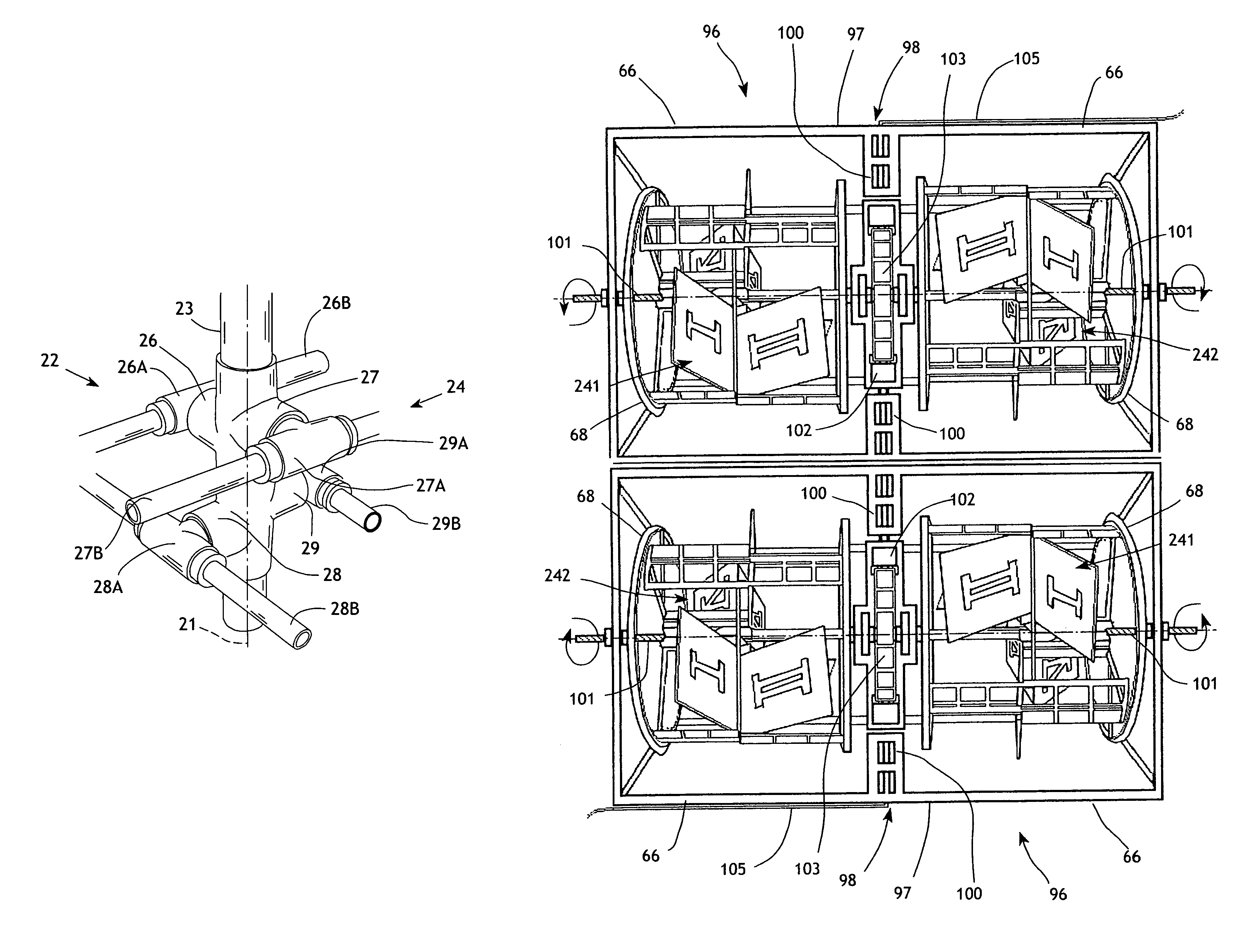
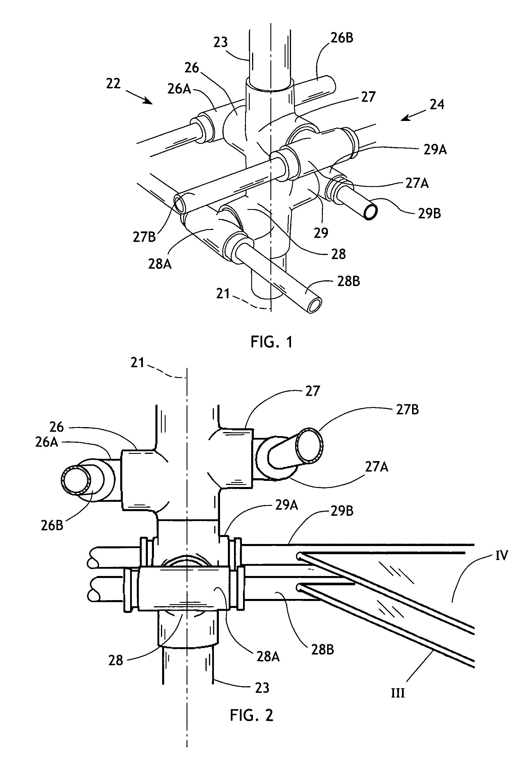
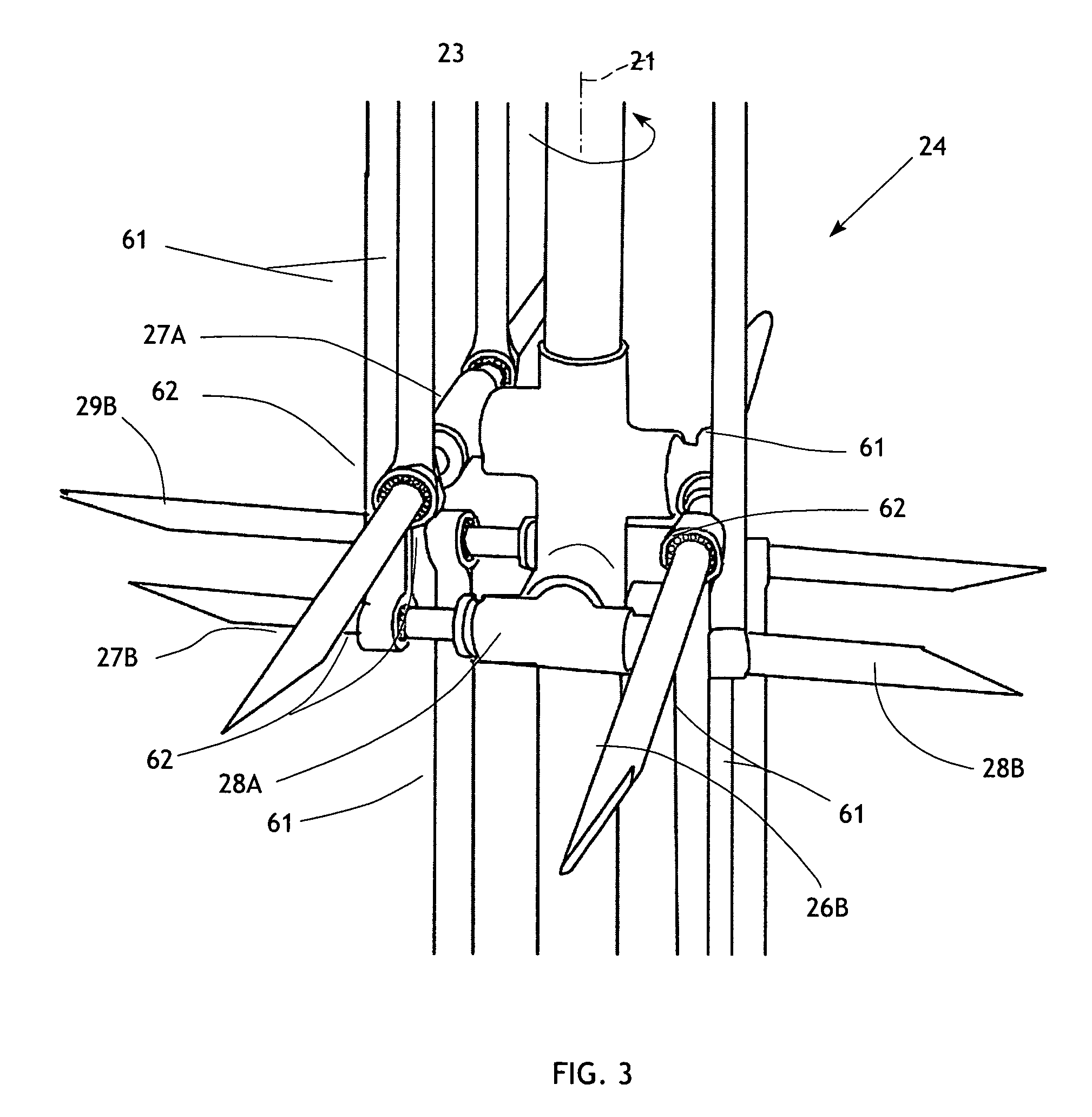
[0043]The present invention generally comprises a wind turbine that is designed to maximize the amount of energy extracted from the ambient wind currents. The wind turbine is constructed as a modular cylindrical assembly having an axis 21 about which it rotates when impinged on by wind or any airflow passing thereby. With regard to FIGS. 1-3, a central component of the wind turbine is a central drive shaft assembly 22 extending coaxially with axis 21 and adapted to rotate thereabout. The drive shaft assembly preferably comprises a hollow drive shaft 23 adapted to be connected to perform useful work, as will be described below. The drive shaft 23 is provided with a hub portion 24 comprised of four bosses 26, 27, 28, and 29 extending generally radially from the drive shaft. The bosses 26 and 27 are disposed in diametrically opposed, axially offset relationship, and the bosses 28 and 29 are similarly disposed but angularly offset 90° about the axis 21 from the bosses 26 and 27, as show...


PUM


Abstract

A wind turbine includes a quartet of pivot shafts in paired parallel relationship and transversely mounted on a central drive shaft, each pivot shaft supporting a pair of wings at opposed ends thereof, the wings offset by 90°. Each pivot shaft rotates cyclically through 90° to move each wing from a wind-engaging orientation (drive position) in which the wing presents a flat surface approximately transverse to the incident wind, to a minimum drag position (glide position). The wings of each pair of pivot shafts open into the drive position at the same time and rotational angle of the turbine. A backstop at the site of each drive position transfers force from each wing to the central drive shaft.

Description

CROSS-REFERENCE TO RELATED APPLICATIONS[0001]This application claims the priority date benefit of U.S. Provisional Application No. 61 / 205,359, filed Jan. 16, 2009.FEDERALLY SPONSORED RESEARCH[0002]Not applicable.SEQUENCE LISTING, ETC ON CD[0003]Not applicable.BACKGROUND OF THE INVENTION[0004]1. Field of the Invention[0005]This invention relates to wind turbines and, more particularly, to wind turbine designs that maximize the frontal contact area of the turbine wings with the wind incident thereon.[0006]2. Description of Related Art[0007]The recent renewed interest in renewable energy sources has highlighted wind energy and the use of wind turbines to generate electrical power by harnessing the energy of wind currents. Indeed, many very large turbines have been installed or are being built around the world, typically employing towers 50 meters or more in height and turbine blades that may exceed 30 meters in length. These installations are successful in generating large amounts of e...

Claims


Application Information

Patent Timeline
Patent Type & Authority Patents(United States)
IPC IPC(8): F03B13/00H02P9/04
CPCF03D3/002F03D3/02H02K57/003F03D3/068F05B2240/40Y02E10/74H02K99/10F03D9/25F03D9/32F03D80/70
Inventor GRIGG, CHARLES
Owner GRIGG CHARLES
Why Eureka
Try Eureka