Drive device

a technology of a drive device and a drive shaft, which is applied in the direction of vehicle maintenance, vehicle cleaning, transportation and packaging, etc., to achieve the effects of convenient damage, improved protection from damage, and large installation space requirements

Active Publication Date: 2013-02-12
ROBERT BOSCH GMBH
View PDF8 Cites 23 Cited by
  • Summary
  • Abstract
  • Description
  • Claims
  • Application Information

AI Technical Summary

Benefits of technology

[0004]The invention has recognized that a diaphragm which is arranged on the housing upper side can be easily damaged, and to protect the diaphragm, it is necessary to provide a separate protective cover, as a result of which in turn the drive device is of tall construction, and therefore the installation space requirement is large. To avoid these disadvantages, the concept of the invention proposes that the diaphragm be arranged laterally on the housing, that is to say on a peripheral wall section of the housing which encloses an angle with the housing upper side, that is to say the areal extent of the housing upper side. The diaphragm should preferably be attached to that housing side to which the motor housing of the electric motor of the drive device is also fixed. Several advantages are surprisingly simultaneously obtained as a result of the lateral arrangement of the at least one diaphragm. Firstly, on account of a lateral, in particular partially hidden arrangement, the diaphragm is better protected from damage, as a result of which it is possible to dispense with a separate protective lid for the diaphragm. In this way, the installation space requirement is reduced, as a result of which the drive device designed according to the concept of the invention can be mounted even under restricted spatial conditions. It is a further advantage that, if the drive device is mounted such that the diaphragm encloses an angle with the horizontal when the drive device is in the mounted state, water impinging on said diaphragm can easily flow off the diaphragm and therefore cannot block the diaphragm.
[0005]In one refinement of the invention, it is advantageously provided that the housing section in which the air-exchange hole which is closed off by the diaphragm is formed runs at least approximately at right angles, that is to say at a 90° angle, to the in particular large-area housing upper side, as a result of which the risk of damage to the diaphragm during the installation of the drive device is further minimized.
[0006]An embodiment is particularly advantageous in which the diaphragm which is fixed into or onto the housing side section also runs at least approximately perpendicular, that is to say at right angles, to the areal extent of the housing upper side in order that water which impinges on the diaphragm can flow off more easily when the drive device is in the mounted state, in which the housing upper side is preferably aligned at least approximately horizontally.
[0009]A drive device designed in this way makes it possible in particular for the diaphragm to be covered laterally at least in sections by the motor housing—in particular such that an air gap of preferably less than 5 mm remains between the motor housing and the diaphragm or the collar of the housing lid, in order to enable an exchange of air between the interior of the gearing housing and the environment. The motor housing, which is preferably produced as a deep-drawn part from metal, therefore serves to protect the diaphragm from damage, in particular during assembly. At least that section of the motor housing end side which covers the diaphragm advantageously extends at least approximately parallel to the housing side section which holds the diaphragm.
[0011]In a second, preferred alternative, the diaphragm is firstly encapsulated with plastic in a preceding injection-molding process in order to form a support frame for the diaphragm, with the unit composed of support frame and diaphragm being encapsulated in a subsequent injection-molding process during the production of the housing lid. The injection preform (diaphragm+support frame) may for this purpose be placed, as an insert part, into a gearing housing lid tool and sealingly encapsulated. The encapsulation of the diaphragm in a preceding injection-molding step, that is to say the production of an injection preform, is advantageous since the tool temperature of the small tool which is required for this purpose is lower, and therefore the workpiece, that is to say the injection preform, can cool down more quickly. In this way, damage to the diaphragm, which can withstand relatively high temperatures only for a short time, is advantageously minimized. In addition or as an alternative to the encapsulation of the plastic frame of the diaphragm by injection molding, it is possible for the plastic frame to be fixed in a positively locking manner to the housing section of the gearing housing, in particular to the collar of the gearing housing lid. For this purpose, the opening edge which holds the support frame may be of corrugated design at least in sections.

Problems solved by technology

A further problem addressed is that of proposing a motor vehicle having a correspondingly improved drive device.

Method used


Image

  • Drive device
  • Drive device
  • Drive device

Examples


Embodiment Construction

[0019]In the figures, identical components and components having the same function are denoted by the same reference numerals.

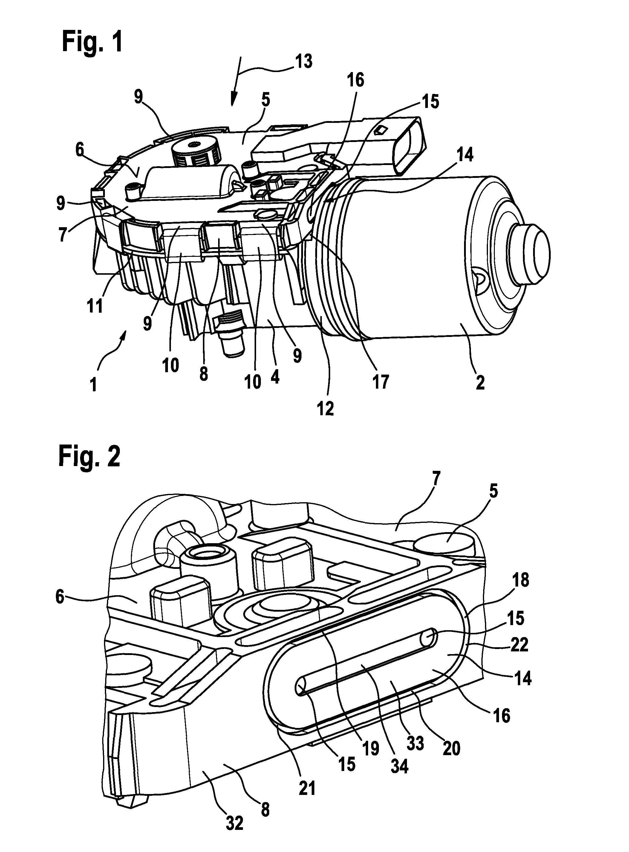
[0020]FIG. 1 shows a drive device 1 of a windscreen wiper system in a motor vehicle. The drive device comprises an electric motor (not shown) which is arranged in a motor housing 2 (pole housing) and also comprises a gearing (worm gearing, not shown) which is arranged in a gearing housing 3 for the oscillating actuation of a wiper arm. Here, the electric motor is in torque-transmitting engagement with the gearing.

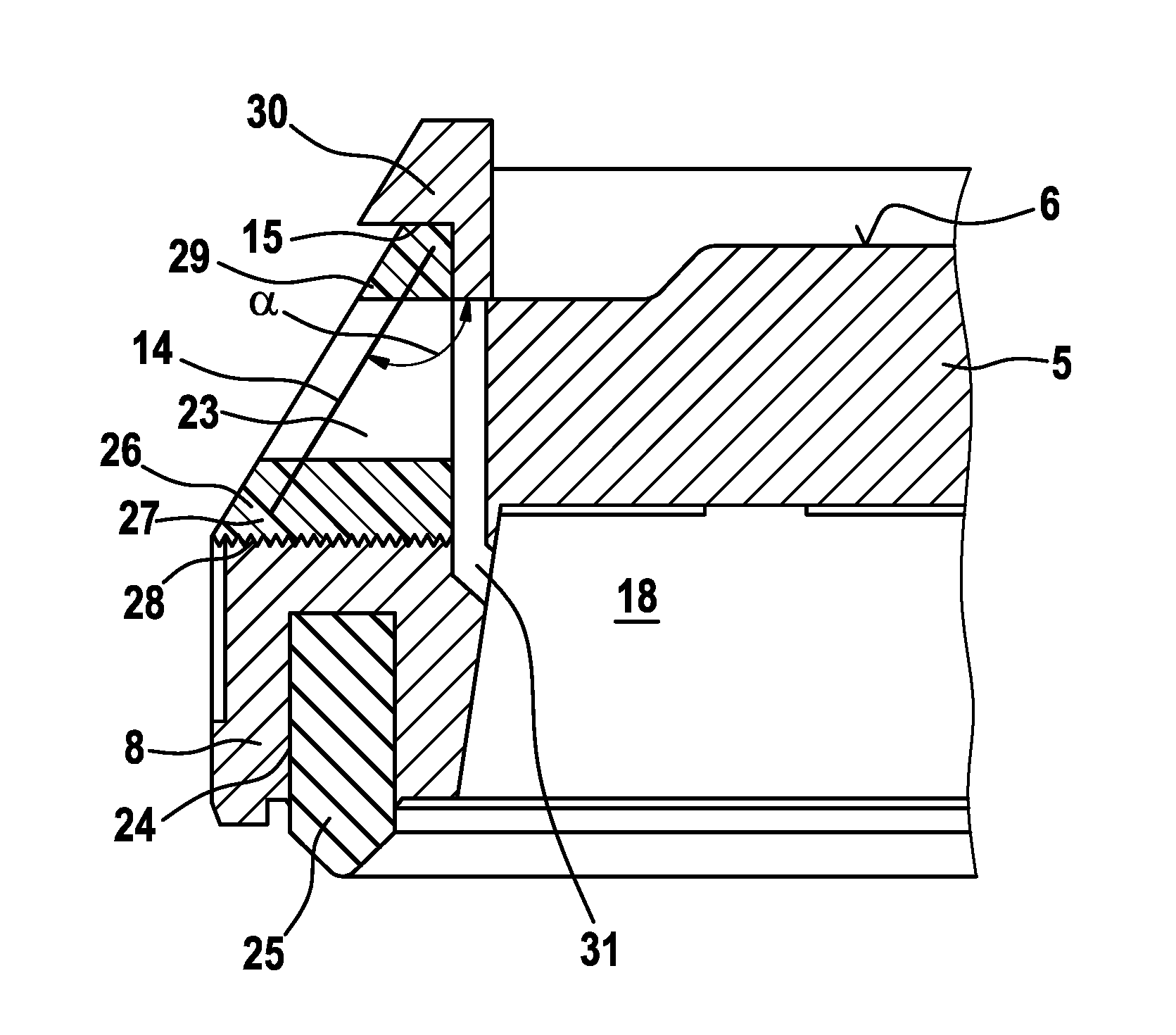
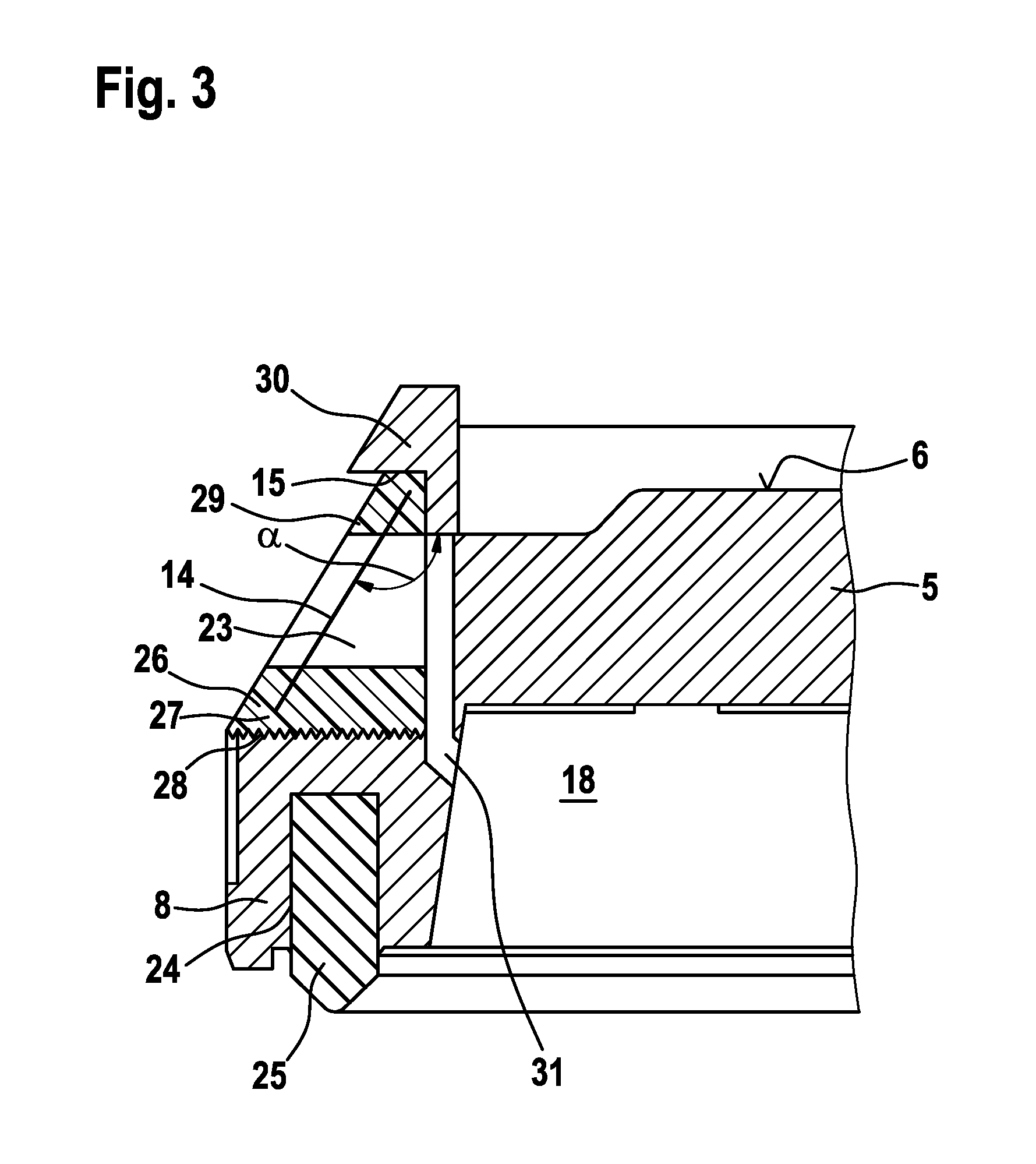
[0021]The gearing housing 3 comprises a trough-like base 4 composed of pressure-die-cast aluminum, and a plastic housing lid 5 which is fixed to the base 4. Both the base 4 and also the housing lid 5 are formed from plastic. Here, a housing lid surface 6 defines a housing upper side 7, with an encircling collar 8 running at right angles to the housing lid surface 6. The collar is provided with recesses 9 which are spaced apart in the peripheral direc...


PUM


Abstract

The invention relates to a drive device (1), in particular for window wiping devices in motor vehicles, having a motor housing (2) which is fixed to a gearbox housing (3) which has a housing upper side (7), and having an air-permeable diaphragm (14) which closes off an opening (15) which is provided in the gearbox housing (3), said diaphragm (14) having the purpose of equalizing pressure when fluctuations in temperature occur. The invention provides that the diaphragm (14) is arranged on a housing side section (16) which runs at an angle to a housing upper side (7). In addition, the invention relates to a motor vehicle having a mounted drive device (1).

Description

BACKGROUND OF THE INVENTION[0001]The invention relates to a drive device, in particular for windscreen wiper systems in motor vehicles.[0002]Drive devices are known which comprise an electric motor with a motor housing (pole housing), with a gearing, for example a worm gearing, which is arranged in a gearing housing being connected downstream of the motor shaft of the electric motor. Here, the motor housing is conventionally fixed laterally to the gearing housing, with it being possible for an exchange of air to take place between the interior volume of the motor housing and the interior volume of the gearing housing. During the operation of the drive device, the air within the motor housing and therefore also within the gearing housing warms up. To prevent an undesired pressure rise within the motor housing and / or within the gearing housing, it is known to arrange a diaphragm, which is permeable to air yet water-repellent, in a housing upper side which is generally formed by a plas...

Claims


Application Information

Patent Timeline
Patent Type & Authority Patents(United States)
IPC IPC(8): H02K5/10F16H57/027
CPCB60S1/166F16H57/027H02K7/1166H02K5/10Y10T74/2186H02K2205/09
Inventor WEGNER, NOBERTMUELLER, ANDREAS
Owner ROBERT BOSCH GMBH
Why Eureka
Try Eureka