Energy storage system with a protective device that chemically binds decomposition products of a solvent of an electric component

a technology of energy storage system and protective device, which is applied in the direction of electrochemical generator, secondary cell servicing/maintenance, transportation and packaging, etc., to achieve the effect of preventing overheating and suppressing a generation of flames

Inactive Publication Date: 2013-02-12
CONTINENTAL AUTOMOTIVE GMBH
View PDF38 Cites 0 Cited by
  • Summary
  • Abstract
  • Description
  • Claims
  • Application Information

AI Technical Summary

Benefits of technology

[0003]The object of the invention is to provide an energy storage system that avoids the escape of decomposition products of solvents which present a hazard to people and the environment.
[0007]Such an energy storage system can for example be usefully employed in the automotive area. In the event of damage, for example a road traffic accident, any decomposition products of the solvent can be bound in the electric component and retained. This protects passengers and the environment against possible dangers from the decomposition products. Such an energy storage system makes it possible to use a solvent in the electric component without any danger.
[0008]The energy storage system can additionally have a protective facility comprising a coating of the housing. The housing can feature an inner side facing towards the electric component on which the coating is present. If a decomposition product of the at least one solvent gets out of the electric component into the interior it is chemically bound to the inner side of the housing by the protective facility, the coating. Especially in the event of damage which leads to the housing being damaged, this avoids decomposition products of the solvent getting into the environment. An outflow of decomposition products from the damaged housing is completely or largely avoided.
[0018]In a further embodiment the chemical compound can be introduced by means of the gas into the space when the closure of the container is opened. The sensor activates the closure of the container, which opens on detection of a signal by the sensor. The gas located in the container and the chemical compound for binding the decomposition products of the solvent can thus be transferred into the interior of the housing since there is an overpressure in the container compared to in the interior. The chemical compounds bind the decomposition products of the solvent escaping from the electric component in the interior of the housing. The gas used for introducing the compound can additionally suppress a generation of flames if necessary and cool down the interior and thereby protect against overheating. The sensor can furthermore also be activated mechanically, in order if necessary, for example during fitting or removal of the energy storage system, to prevent an escape of the decomposition products of the solvent.
[0019]In a further embodiment a facility is present on the housing for equalizing the pressure between the interior of the housing and the surroundings of the energy storage system. Such a facility can comprise a predetermined breaking point in the housing which creates an opening in the housing for controlled equalization of the pressure in the event of overpressure. Such a predetermined breaking point can for example comprise a rupture disc which ruptures if the pressure in the interior becomes too great, or a valve element which releases the overpressure into the surroundings in a controlled manner. This avoids the overall housing being damaged on introduction of the gas and the chemical compounds from the container into the interior and too great an overpressure in the interior of the housing leading to an explosive destruction of the housing.

Problems solved by technology

Possible instances of damage are for example mechanical damage to the energy storage system, an electrical defect which triggers a short circuit for example, an overload as a result of defective charge regulation or thermal overheating caused by a fire for example.

Method used


Image

  • Energy storage system with a protective device that chemically binds decomposition products of a solvent of an electric component
  • Energy storage system with a protective device that chemically binds decomposition products of a solvent of an electric component
  • Energy storage system with a protective device that chemically binds decomposition products of a solvent of an electric component

Examples


Embodiment Construction

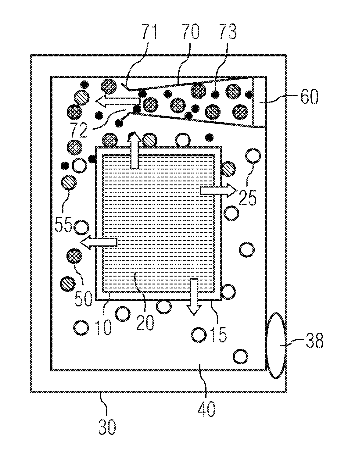
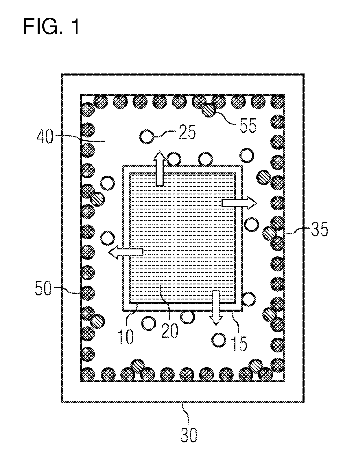
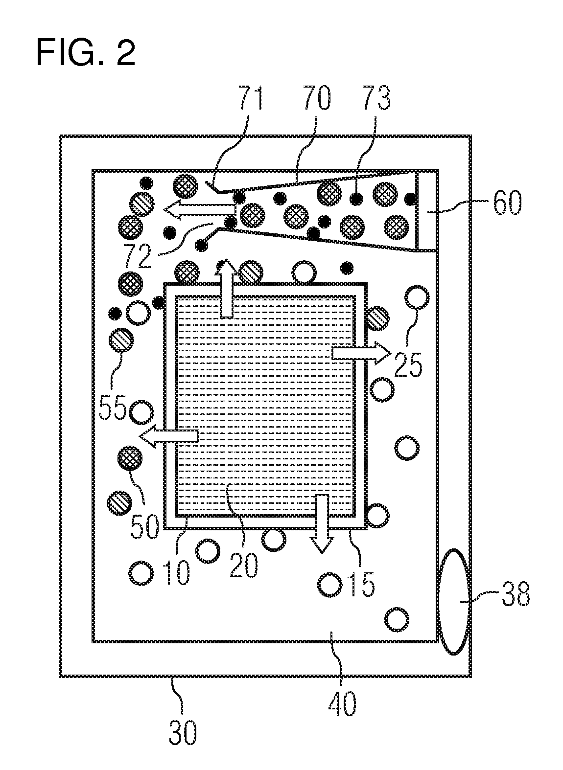
[0026]FIG. 1 shows the schematic side view of an exemplary embodiment of the energy storage system. The electric component 10 containing a solvent 20, for example acetonitrile, is located in the interior 40 of the housing 30. The electric component is surrounded by an envelope 15 which separates the solvent from the inside of the housing. The housing has an inner side 35 facing towards the electric component. On the inner side of the housing there is a coating which consists of the chemical compound 50 for binding the decomposition products. The coating can also contain a matrix, for example a binding agent, in which the chemical compounds 50 are to be found. Decomposition products 25 of the solvent 20, especially gaseous decomposition products, can escape from the electric component 10, for example if the energy storage system is damaged or vibrated, a process which is indicated schematically by the arrows on the electric component. As soon as the decomposition products 25 of the s...


PUM

PropertyMeasurementUnit
electric componentaaaaaaaaaa
pressureaaaaaaaaaa
volumeaaaaaaaaaa

Abstract

An energy storage system includes an electric component, a solvent, and a protective device which chemically binds the decomposition products of the solvent. Any damage to the surroundings, which could be caused by the decomposition products of the solvent, can be prevented using the novel energy storage system.

Description

BACKGROUND OF THE INVENTIONField of the Invention[0001]The invention relates to energy storage system containing an electric component, a housing and a protective device.[0002]Electric components, such as dual-layer capacitors for example, feature solvents which can be problematic for the safety of people and for the environment. Above all, in the event of the electric component sustaining damage, these solvents or decomposition products of these solvents can get into the environment. To avoid this it is necessary to prevent these hazardous substances escaping into the environment.BRIEF SUMMARY OF THE INVENTION[0003]The object of the invention is to provide an energy storage system that avoids the escape of decomposition products of solvents which present a hazard to people and the environment.[0004]This object is achieved by an energy storage system according to recited in the independent claim. Further developments of the energy storage system are the subject matter of further cla...

Claims


Application Information

Patent Timeline
Patent Type & Authority Patents(United States)
IPC IPC(8): H01G9/00H01M10/34H01M10/52
CPCH01G9/08H01G9/155H01M10/4235H01M10/52Y02E60/13Y02T10/7022Y02T10/70Y02E60/10H01G11/20H01G11/78
Inventor BAUR, FRANKGOTTE, CARSTEN
Owner CONTINENTAL AUTOMOTIVE GMBH
Why Eureka
Try Eureka