Optical fiber with single layer coating for field termination

a technology of optical fiber and coating, applied in the direction of cladded optical fiber, glass optical fiber, instruments, etc., can solve the problems of affecting the quality and life of optical fiber, the termination process is relative delicate, and the damage of optical fiber,

Active Publication Date: 2013-02-12
SUCCESS PRIME +1
View PDF7 Cites 5 Cited by
  • Summary
  • Abstract
  • Description
  • Claims
  • Application Information

AI Technical Summary

Problems solved by technology

It is worth noting that the field termination process is relative delicate task and the optical fiber is susceptible to damages caused by errors, such as, inappropriate tool and parameter adjustment, dust and other abrasion source, human error, and so on.
Once damaged, the quality and the life span of the optical fiber are severely affected.
However, while the above structures provide possible solution to enhance the strength of the optical fiber, these techniques do not address the difficult issue of field termination.
While the optical fiber structure address the issue of connection, one disadvantage of the mentioned structure is that a special cleaver is needed to perform the necessary cleaving so that the cladding layer would be slightly cleaved to enable subsequent snapping of the glass core.
Neither of the above two cleaving alternatives is satisfactory and may impede the optical fiber deployment efficiency and quality.

Method used


Image

  • Optical fiber with single layer coating for field termination
  • Optical fiber with single layer coating for field termination
  • Optical fiber with single layer coating for field termination

Examples


Embodiment Construction

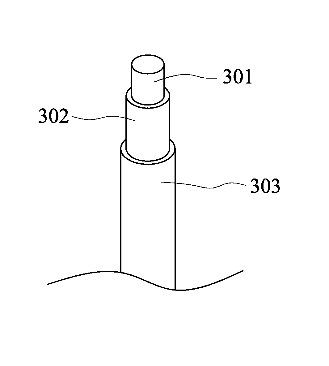
[0016]FIG. 3 shows a schematic view of a structure of optical fiber with single layer coating according to the invention, including a glass core 301, a cladding layer 302 and a permanent coating 303. In order to make the final specification of the optical fiber of the present invention conforms to standard specification, the combined outer diameter (OD) of cladding layer 302 is reduced slightly from the conventional 125 um to ranging from about 109 um to 117 um, and the thickness of permanent coating ranges from about 4 um to 8 um. Hence, the combined outer diameter of the permanent coating will remain 125 um to conform to the standard. It is worth noting the slight diameter reduction of cladding layer 302 will not affect the optical signal transmission in glass core 301 of the optical fiber. It is also worth noting that the optical fiber structure of the present invention does not include a buffer layer. Permanent coating 303 can be, for example, a polymer coating disposed on cladd...


PUM


Abstract

A structure for optical fiber with single layer coating suitable for field termination process is provided, including a glass core, a cladding layer, and a permanent coating protective layer. The thickness of the permanent coating ranges preferably from about 4 um to 8 um, and remains on the optical fiber during the field termination process to provide protection to the optical fiber after the buffer layer is striped off. In addition, the optical fiber structure of the present invention still conforms to the specification of the standard optical fiber. The optical fiber of the structure according to the present invention can simplify the field termination process so that the quality efficiency of the deployment is improved.

Description

FIELD OF THE INVENTION[0001]The present invention generally relates to an optical fiber with a single layer of coating. The optical fiber with single layer coating is applicable to a simplified field termination method.BACKGROUND OF THE INVENTION[0002]The superiority of optical signal in the aspects of bandwidth, security and other physical characteristics, compared to the electrical signal, has made optical fiber a popular choice for signal transmission, in particular, for communication or multimedia applications. FIG. 1 shows a schematic view of a typical optical fiber. As shown in FIG. 1, A typical optical fiber includes a glass core 101, a cladding layer 102 and a buffer layer 103. Glass core 101 is the part where the optical signal actually travels. Because glass core 101, cladding layer 102 is extremely fragile and susceptible to the surface abrasion, buffer layer 103 are needed to provide protection to glass core 101. In particular, during deployment, the field termination mu...

Claims


Application Information

Patent Timeline
Patent Type & Authority Patents(United States)
IPC IPC(8): G02B6/02B05D5/06
CPCG02B6/02395
Inventor CHOU, KUEI-HUANGTZENG, SHING-WU PAULWU, CHIH-YUHSU, SHENG-HSIANG
Owner SUCCESS PRIME
Why Eureka
Try Eureka