
Control method, apparatus of peak amplifier and doherty power amplifier

a technology of peak amplifier and control method, which is applied in the direction of gated amplifiers, amplifiers with semiconductor devices/discharge tubes, amplifiers, etc., can solve the problems of increasing the power consumption of the peak power amplifier is very small, and the power consumption of the peak power amplifier is 10%-20%, so as to reduce power consumption, improve efficiency, and reduce power consumption

Inactive Publication Date: 2013-05-23
ZTE CORP
View PDF4 Cites 0 Cited by
  • Summary
  • Abstract
  • Description
  • Claims
  • Application Information

AI Technical Summary

Benefits of technology

The technical effect of this patent is to provide a method and apparatus for controlling a peak amplifier and a Doherty power amplifier that reduces peak power consumption and increases efficiency. This is achieved by avoiding the disadvantageous approach of turning on the peak amplifier in advance when the carrier amplifier starts to compress, by controlling the turn-on time of the peak amplifier based on the input signal level. This method results in a more efficient power amplifier design, with lower power consumption and improved linearity and efficiency. Additionally, the method is cost-effective and can be easily integrated into existing power amplifier designs.

Problems solved by technology

While the traditional Doherty power amplifier has a disadvantage, that is, in theory, the power consumption of the peak power amplifier of the Doherty power amplifier is very small; however, in the actual power amplifier, the power consumption of the peak power amplifier accounts for 10%-20%.
While a class C amplifier is turned on gradually with a signal from small to large, and therefore, in the actual application, in order to enable the peak amplifier to be turned on completely when the carrier amplifier starts to compress, the peak amplifier must be turned on ahead of time at a lower level, thus increasing the power consumption of the peak power amplifier, and reducing the efficiency of the whole power amplifier.

Method used


Image

  • Control method, apparatus of peak amplifier and doherty power amplifier
  • Control method, apparatus of peak amplifier and doherty power amplifier
  • Control method, apparatus of peak amplifier and doherty power amplifier

Examples


Embodiment Construction

[0037]The embodiments of the present invention reduce the power consumption of peak amplification by controlling turn-on and turn-off of a signal of a peak amplification branch of a Doherty power amplifier, thus enhancing the efficiency of the whole power amplifier.

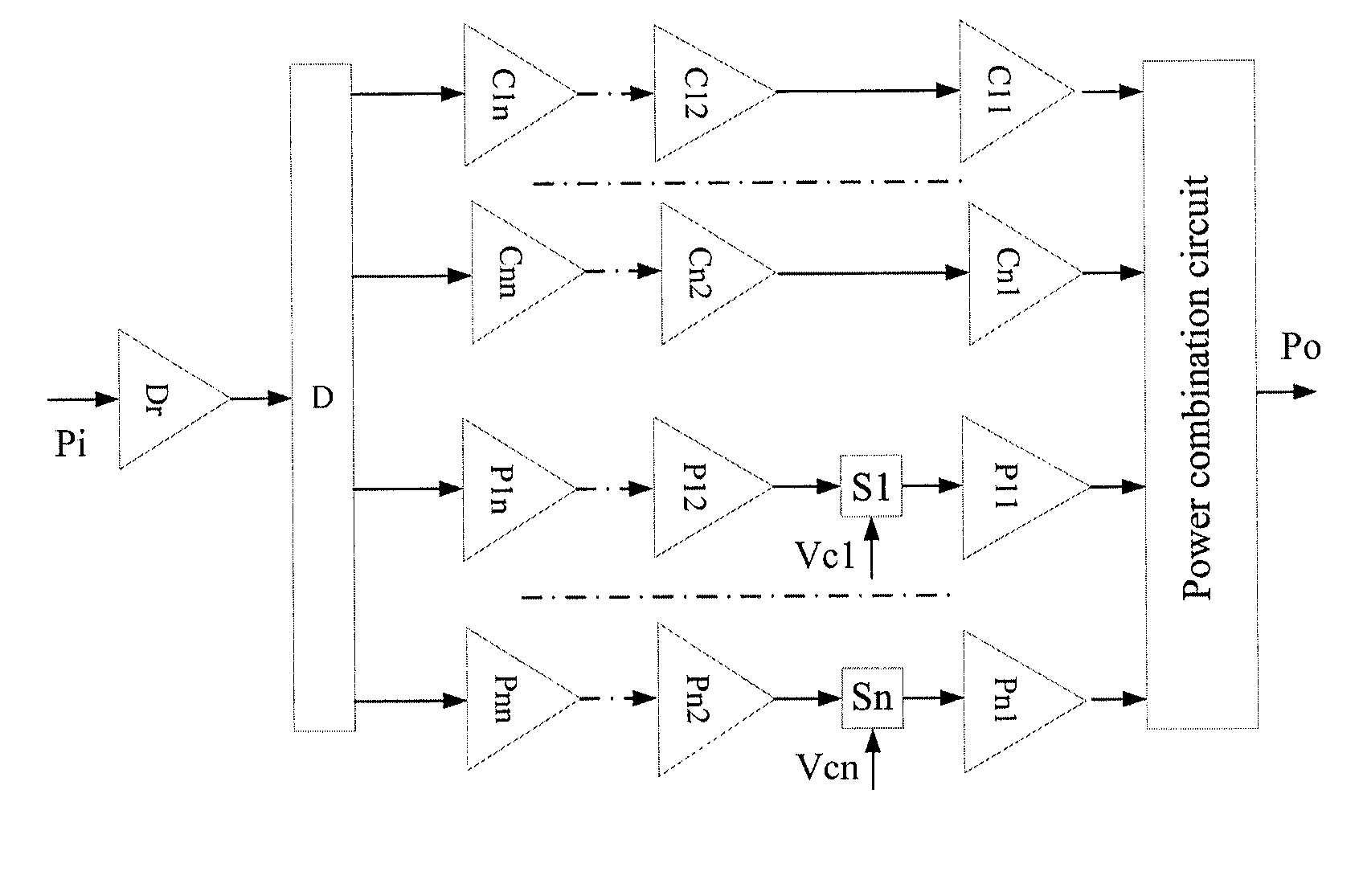
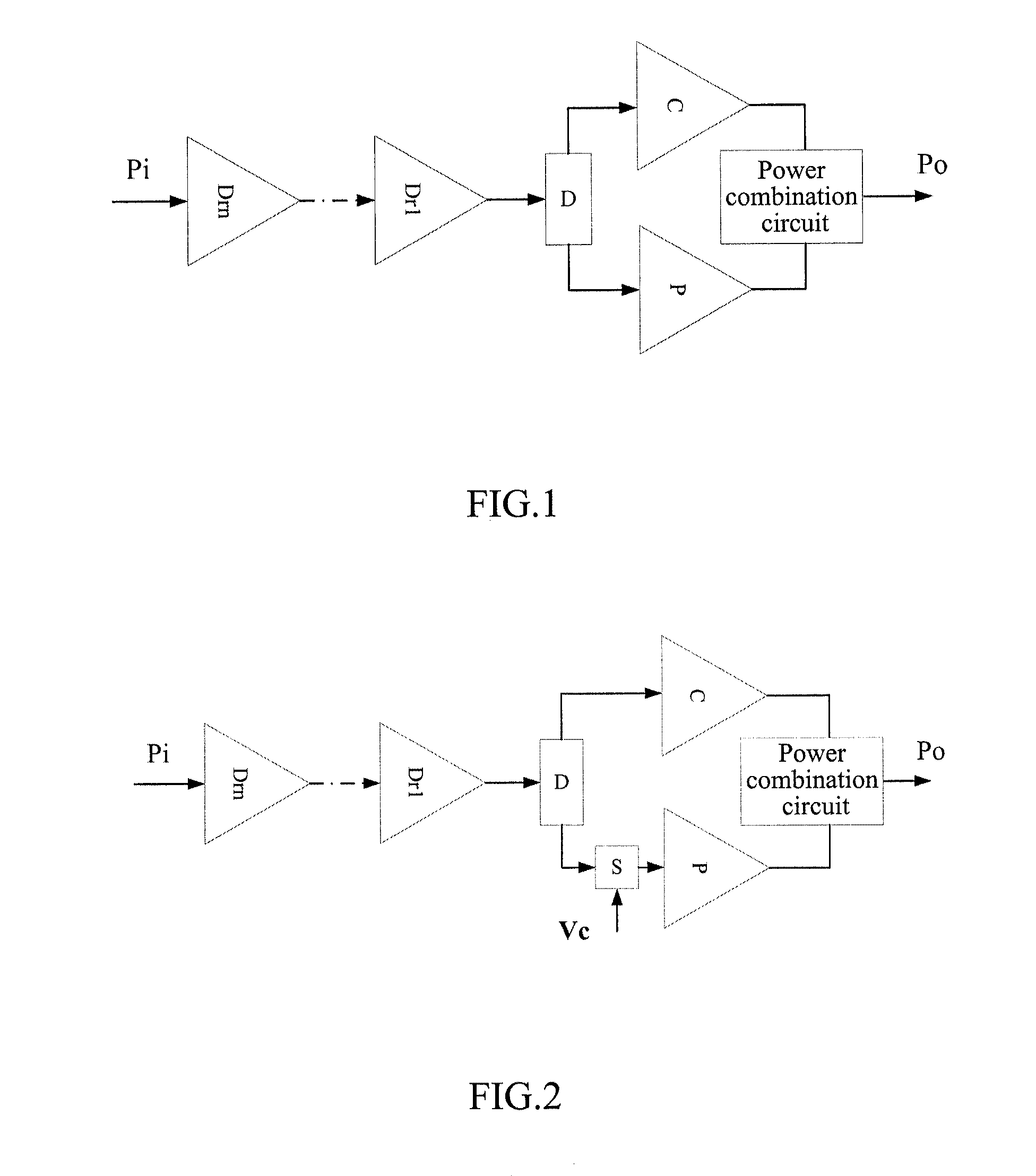
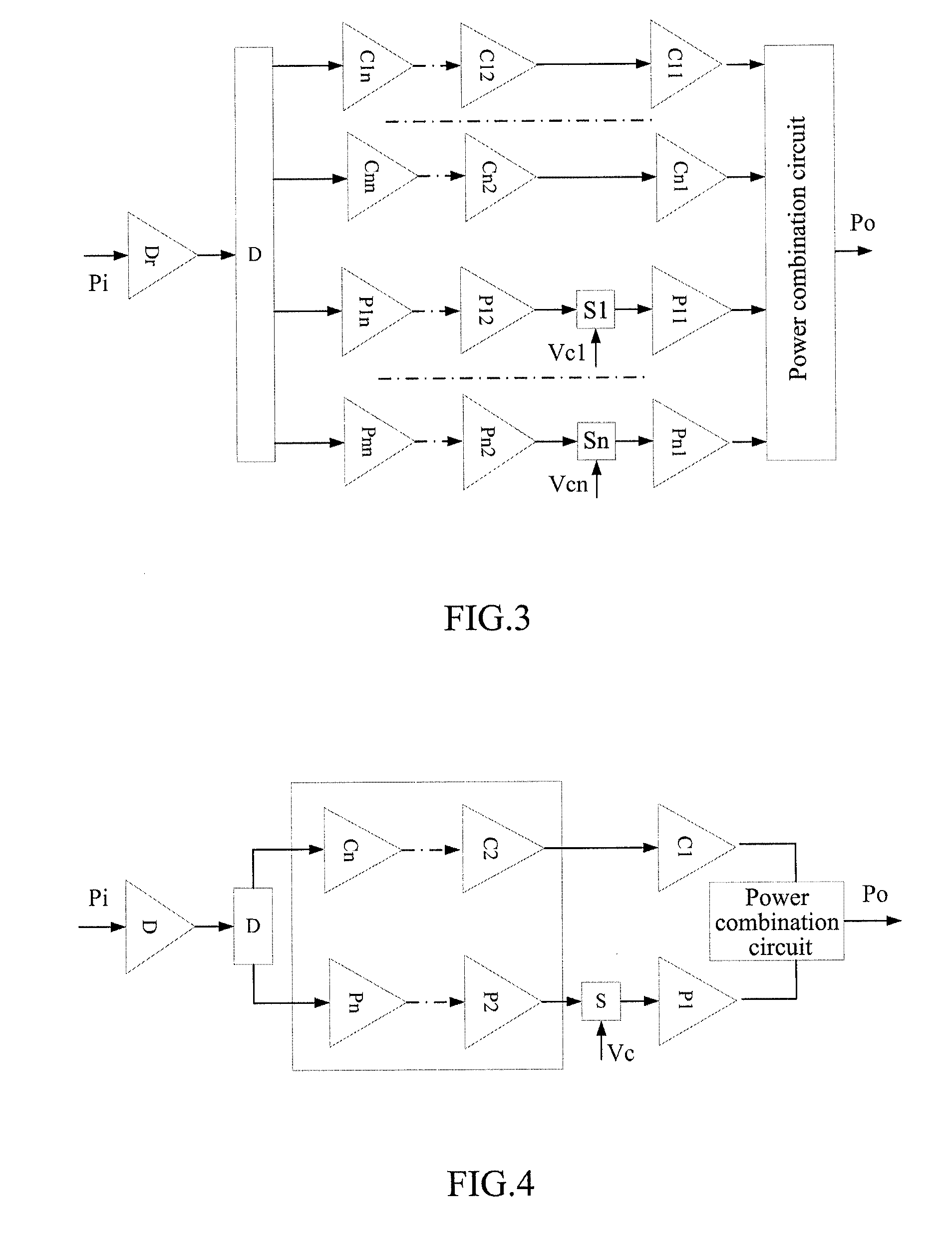
[0038]Based on the above idea, the embodiments of the present invention use the following technical scheme: a RF switching circuit being added in the peak amplification branch of the Doherty power amplifier, and a RF switch being turned on when an input signal of the peak amplification branch is increased to a suitable amplitude, which results in the peak amplifier being turned on, it avoids the peak amplifier from being turned on ahead of time, thus reducing the power consumption of the peak power amplifier and enhancing the efficiency of the whole power amplifier.

[0039]The examples of the present invention will be described in detail in conjunction with accompanying drawings hereinafter. It should be illustrated that in...


PUM


Abstract

A control method and apparatus of a peak amplifier of a Doherty power amplifier are disclosed, wherein, the control apparatus includes a Radio Frequency (RF) switching circuit in a peak amplification branch of the Doherty power amplifier, which is used to control the turn-on and turn-off of the peak amplifier in the peak amplification branch. The method and apparatus avoid a disadvantage that the peak branch in the Doherty power amplifier is turned on ahead of time, thus reducing the power consumption of the peak power amplifier, and enhancing the mass efficiency of the whole power amplifier; and largely reducing the product expense and production expense of the power amplifier compared to the scheme of some manufacturers improving on-time of the peak power amplifier using complex digital circuits.

Description

TECHNICAL FIELD[0001]The present invention relates to the technical field of a power amplifier at a base station, and in particular, to a method, apparatus for controlling a peak amplifier and a Doherty power amplifier.BACKGROUND OF THE RELATED ART[0002]With greens environmental protection and low-carbon economy concepts becomes deeply rooted among the people continuously around the world, requirements of operators for reduction of power consumption of a wireless communication system also become increasing high. In the wireless communication system, a Radio Frequency (RF) power amplifier (power amplifier for short) in a base station device is one of core modules of the whole system, and an important index of the RF power amplifier is the efficiency of the power amplifier. It is indicated from data analysis that in the whole base station device, the energy consumption of the power amplifier portion accounts for about 60% of the overall energy consumption, and therefore, enhancing the...

Claims


Application Information

Patent Timeline
IPC IPC(8): H03G1/00
CPCH03F1/0277H03F1/0288H03F3/211H03F3/72H03F2200/507H03F2203/21106H03F2200/405H03F2203/21196H03F2203/7206H03F2203/7236H03F3/245H03G1/0088H03F3/195H03F2203/21142
Inventor CHEN, HUAZHANGLIU, JIANLIAN, JINYUANCUI, XIAOJUN
Owner ZTE CORP
Learn More