Device for detecting and monitoring damage to anti-friction bearings

a technology for bearings and sensors, applied in mechanical devices, instruments, transportation and packaging, etc., can solve the problems of restrictions on measuring possibilities and expensive devices, and achieve the effect of less expenditure and less cos

Active Publication Date: 2013-02-19
ROTHE ERDE GMBH
View PDF14 Cites 6 Cited by
  • Summary
  • Abstract
  • Description
  • Claims
  • Application Information

AI Technical Summary

Benefits of technology

[0005]Now, therefore, it is the object of the present invention to configure the device of the initially designated species in such a manner that it can be manufactured at less expenditure, thus being less costly and requiring no circumferential grooves.
[0007]The present invention bears an advantage in that the second coil only needs to be inductively coupled over a very small part of the bearing circumference to a first coil allocated to it and accommodated in the anti-friction bearing chamber. Energy transferred during the inductive coupling can be stored in an energy accumulator connected to the first coil and, if properly dimensioned, it is sufficient to take the desired measurements. Analogously it is possible to store emitted measuring data intermediately in a data memory and to transfer the data only if both coils stand opposite to each other. Therefore, the hardened area allocated to the anti-friction bearing chamber needs to be interrupted only in the area of a small bore accommodating the second coil. As the additionally required electronic components take little impact on overall costs, it results a low-cost flexibly applicable monitoring device.

Problems solved by technology

However, such devices are considered expensive in that the circumferential groove destined to accommodate the induction coil must be configured in the mostly hardened area of the relevant bearing ring, the area facing the anti-friction bearing chamber.
Irrespective thereof, it is only possible to accommodate a maximum of two induction coils for lack of space, thus entailing restrictions with regard to measuring possibilities.

Method used


Image

  • Device for detecting and monitoring damage to anti-friction bearings
  • Device for detecting and monitoring damage to anti-friction bearings
  • Device for detecting and monitoring damage to anti-friction bearings

Examples


Embodiment Construction

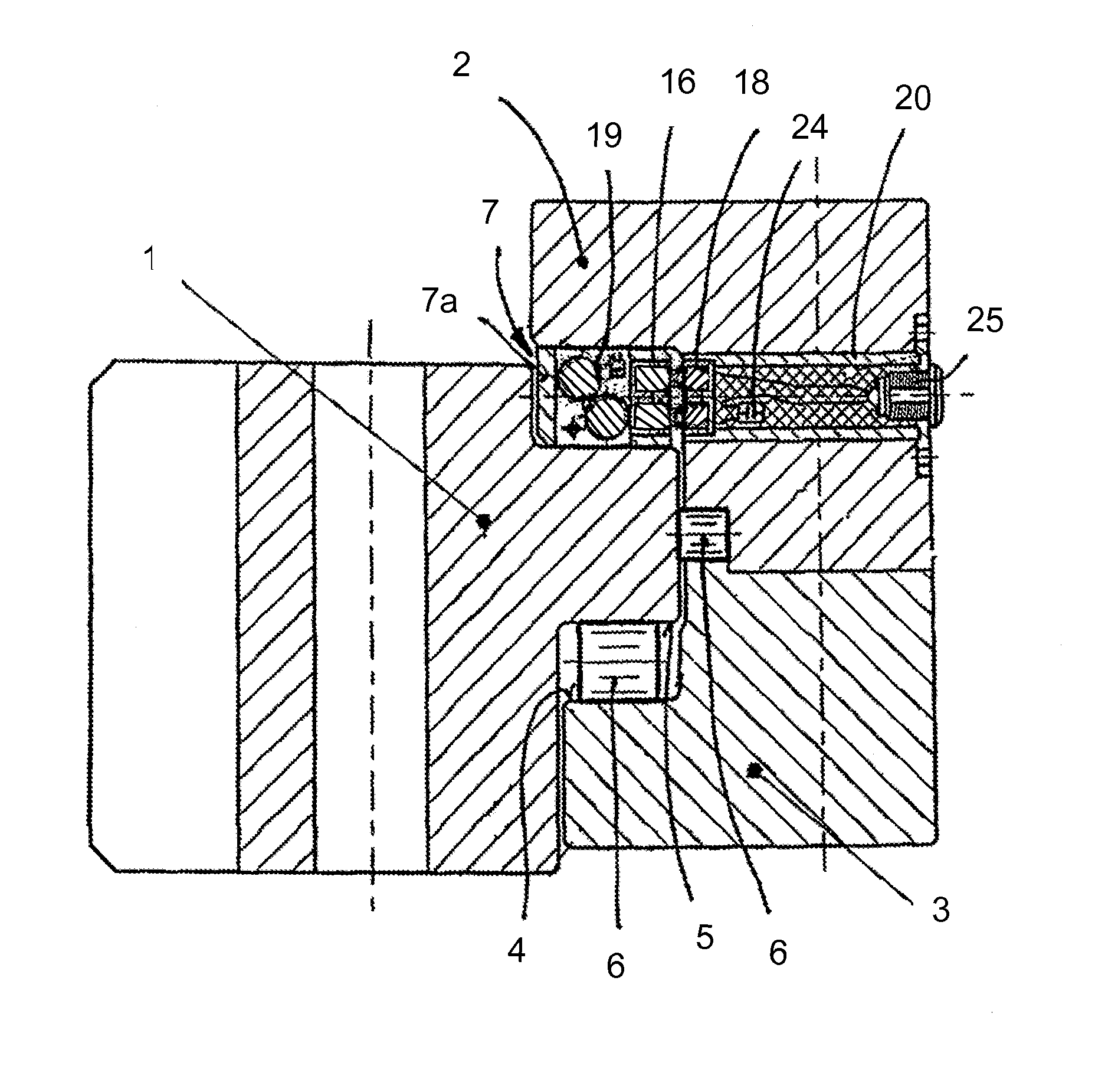
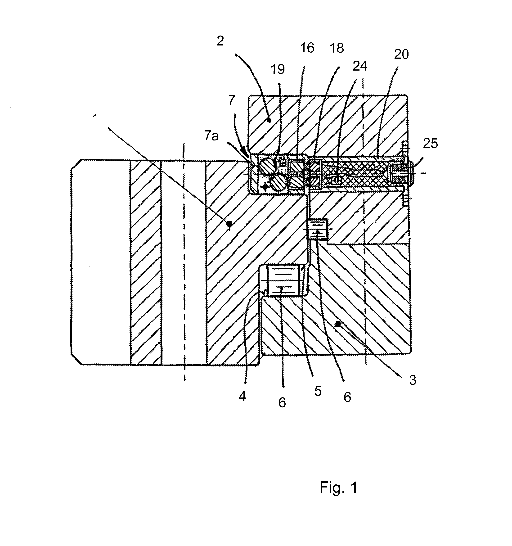
[0024]Referring to the drawings in particular, the embodiment example of the inventive device as schematically represented in FIG. 1 shows a large-size anti-friction bearing comprised of a turnable bearing ring 1, a stationary bearing ring 2, and a retainer ring 3 which is rigidly connected to the afore-mentioned rings, in between of which anti-friction bearing chambers are provided at three levels. These anti-friction bearing chambers are bordered by races 4, 5 for anti-friction bearing bodies 6 here configured as cylinder rolls. Moreover, to guide and separate the anti-friction bearing bodies 6, cages 7 are provided for in the anti-friction bearing chambers as shown in FIG. 1 for the uppermost level only, the cages having webs 7a engaging between the anti-friction bearing bodies 6. Races 4 and 5 as well as the adjacent areas, more particularly the transitions between races 4, 5 and the bearing rings, are basically provided with a hardening layer.

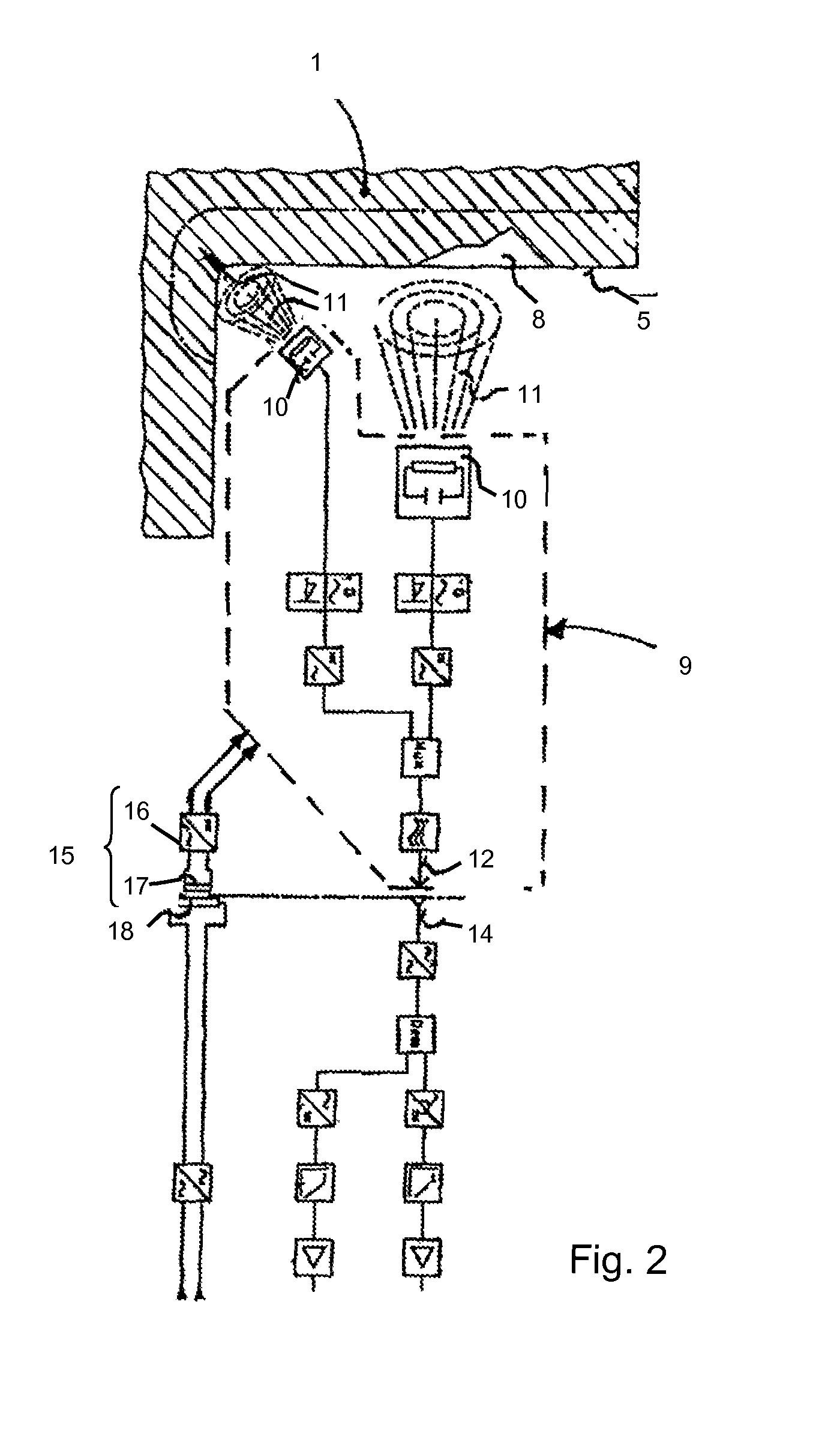
[0025]To monitor races 4 and 5 as w...


PUM

PropertyMeasurementUnit
capacitancesaaaaaaaaaa
electric currentaaaaaaaaaa

Abstract

The invention relates to a device for detecting and monitoring damage to races or adjacent regions of bearing rings (1, 2, 3) of anti-friction bearings. The device includes a measuring device, disposed in the anti-friction bearing chamber, having a sensor and structure for supplying sensor measurement data to the outside. The device has an energy source, which is also disposed in the anti-friction roller bearing chamber and which comprises a first coil (16) for the measuring device and a second coil (18) disposed outside the anti-friction bearing chamber and destined for inductive transfer of electrical energy to the first coil (16). The second coil (18) extends only over a part of the bearing circumference and the energy source comprises an energy accumulator (19) connected to the first coil (16).

Description

CROSS REFERENCE TO RELATED APPLICATIONS[0001]This application is a United States National Phase application of International Application PCT / EP2008 / 002605 and claims the benefit of priority under 35 U.S.C. §119 of German Patent Application DE 10 2007 020 938.1 filed May 4, 2007, the entire contents of which are incorporated herein by reference.FIELD OF THE INVENTION[0002]The invention relates to a device for detecting and monitoring of damage to anti-friction bearings.BACKGROUND OF THE INVENTION[0003]For various applications, more particularly for large-size anti-friction bearings employed in off-shore applications, with cranes or buoys it is purposive to provide testing appliances which, working in non-destructive manner and without requiring a disassembly of the bearing, are capable of detecting cracks at the race and / or adjacent regions of the bearing rings. With a prior art device of the initially designated species (EP 0 529 354 B1), detecting and monitoring of damage to races ...

Claims


Application Information

Patent Timeline
Patent Type & Authority Patents(United States)
IPC IPC(8): F16C32/00G01N27/82G01R33/14H02J7/00
CPCF16C19/52G01M13/04F16C2300/14F16C2233/00
Inventor CLAUS, WOLFGANGWERTHER, WOLFGANG
Owner ROTHE ERDE GMBH
Why Eureka
Try Eureka