Supercharge Your Innovation With Domain-Expert AI Agents!

Metal volume source calibration phantom and calibrating method thereof

a technology of metal volume source and calibration phantom, which is applied in the field of source calibration technology, can solve the problems of large error and considerable consumption of time and storage spa

Inactive Publication Date: 2013-02-19
INST NUCLEAR ENERGY RES ROCAEC
View PDF11 Cites 0 Cited by
  • Summary
  • Abstract
  • Description
  • Claims
  • Application Information

AI Technical Summary

Benefits of technology

This solution provides accurate counting efficiency measurements for nuclear waste materials, reducing errors and time consumption, and enabling efficient calibration of metal waste samples with varying densities.

Problems solved by technology

However, the current waste curie monitors and the calibrating method thereof still have the following shortcomings: (1) a nonmetal calibration phantom is used for measuring the counting efficiency; however, since noncombustible metal wastes upon deregulation are mostly measured in practice, a large error exists between a nonmetal phantom and a metal waste in terms of mass attenuation coefficient and self-shielding effect, and the result of the counting efficiency measurement deviates from the actual value; (2) usually, a single substance is used in the monitor to establish density efficiency, and the fact that the sample is not made up of a single substance is neglected; (3) in the current calibration phantom, metal or nonmetal materials are arranged in a gapless manner, which is different from the loose arrangement of metal wastes, leading to a large error in the result of the counting efficiency measurement; and (4) when calibration phantoms made of different nonmetal materials and with different densities are used to derive the calibration curve, since the phantoms with different densities need to be fabricated using different materials respectively, a long period of time is required for fabricating the phantoms, and certain space is required for storing the finished phantoms, which considerably consumes time and storage space.

Method used


Image

  • Metal volume source calibration phantom and calibrating method thereof
  • Metal volume source calibration phantom and calibrating method thereof
  • Metal volume source calibration phantom and calibrating method thereof

Examples


Embodiment Construction

[0025]In order to make the features, objectives, and functions of the present invention more comprehensible to the Examiner, the related detailed structures and design ideas and reasons of the system of the present invention are illustrated below, so that the Examiner can better understand the characteristics of the present invention. The detailed illustration is as follows.

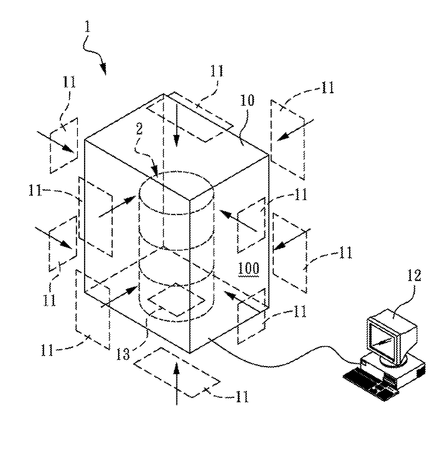
[0026]FIG. 1 is a schematic view of a waste curie monitor and a metal volume source calibration phantom. Referring to FIG. 1, the waste curie monitor 1 has a shielding 10, which is a hexahedron assembly made of lead of the same thickness. An inspection space 100 is formed in the shielding 10. Ten units of the same large-area radioactivity detectors 11 are arranged on wall surfaces inside the inspection space 100. In this embodiment, the radioactivity detector 11 is a plastic scintillation detector. A weight meter is disposed in the inspection space 100 for weighting an object-to-be-tested. The waste curie monitor...


PUM


Abstract

A metal volume source calibration phantom includes a container, a plurality kinds of metal plates stacked up inside the container, and at least one slab of radioactive source, each of which is disposed between the adjacent metal plates and includes a plurality of radionuclides. By means of inserting different numbers of the plurality kinds of metal plates inside the container, it is capable of obtaining the metal volume source calibration phantoms with different densities. In addition, a method for calibrating the metal volume source calibration phantom is also provided, which starts by the step of providing the metal calibration phantoms with different densities by inserting different numbers of a plurality kinds of metal plates and at least one slab of radioactive source into the container, and then detecting counting efficiency with respect to the metal volume calibration phantoms having different densities by a waste curie monitor so as to establish the correlation between density and counting efficiency.

Description

CROSS-REFERENCE TO RELATED APPLICATIONS[0001]This non-provisional application claims priority under 35 U.S.C. §119(a) on Patent Application No(s). 099120752 filed in Taiwan, R.O.C. on Jun. 25, 2010, the entire contents of which are hereby incorporated by reference.BACKGROUND OF THE INVENTION[0002]1. Field of Invention[0003]The present invention relates to a source calibration technology, and more particularly to a metal volume source calibration phantom and a calibrating method thereof, which can directly use metal volume source calibration phantoms with different densities to derive the calibration curve for density and counting efficiency, such that according to the counting efficiency from the multi-density source calibration phantom corresponding to the density of the sample of nuclear wastes to be tested, accurate measurement results can be obtained when measuring the counting efficiency for samples of different nuclear waste materials.[0004]2. Related Art[0005]Currently, waste...

Claims


Application Information

Patent Timeline
Patent Type & Authority Patents(United States)
IPC IPC(8): G12B13/00G01D18/00
CPCG01T1/167G01T1/169
Inventor YEH, CHIN-HSIENYUAN, MING-CHEN
Owner INST NUCLEAR ENERGY RES ROCAEC
Features
  • R&D
  • Intellectual Property
  • Life Sciences
  • Materials
  • Tech Scout
  • Unparalleled Data Quality
  • Higher Quality Content
  • 60% Fewer Hallucinations
Learn More