System and method for measuring retentate in filters

a filter and retentate technology, applied in the direction of electrical control, separation processes, instruments, etc., can solve the problems of inability of systems which are not capable of detecting high soot loads, inability of prior art systems to monitor the spatial distribution of material accumulated in filters, and inability to detect high soot loads

Active Publication Date: 2013-02-26
FILTER SENSING TECH
View PDF38 Cites 33 Cited by
  • Summary
  • Abstract
  • Description
  • Claims
  • Application Information

AI Technical Summary

Benefits of technology

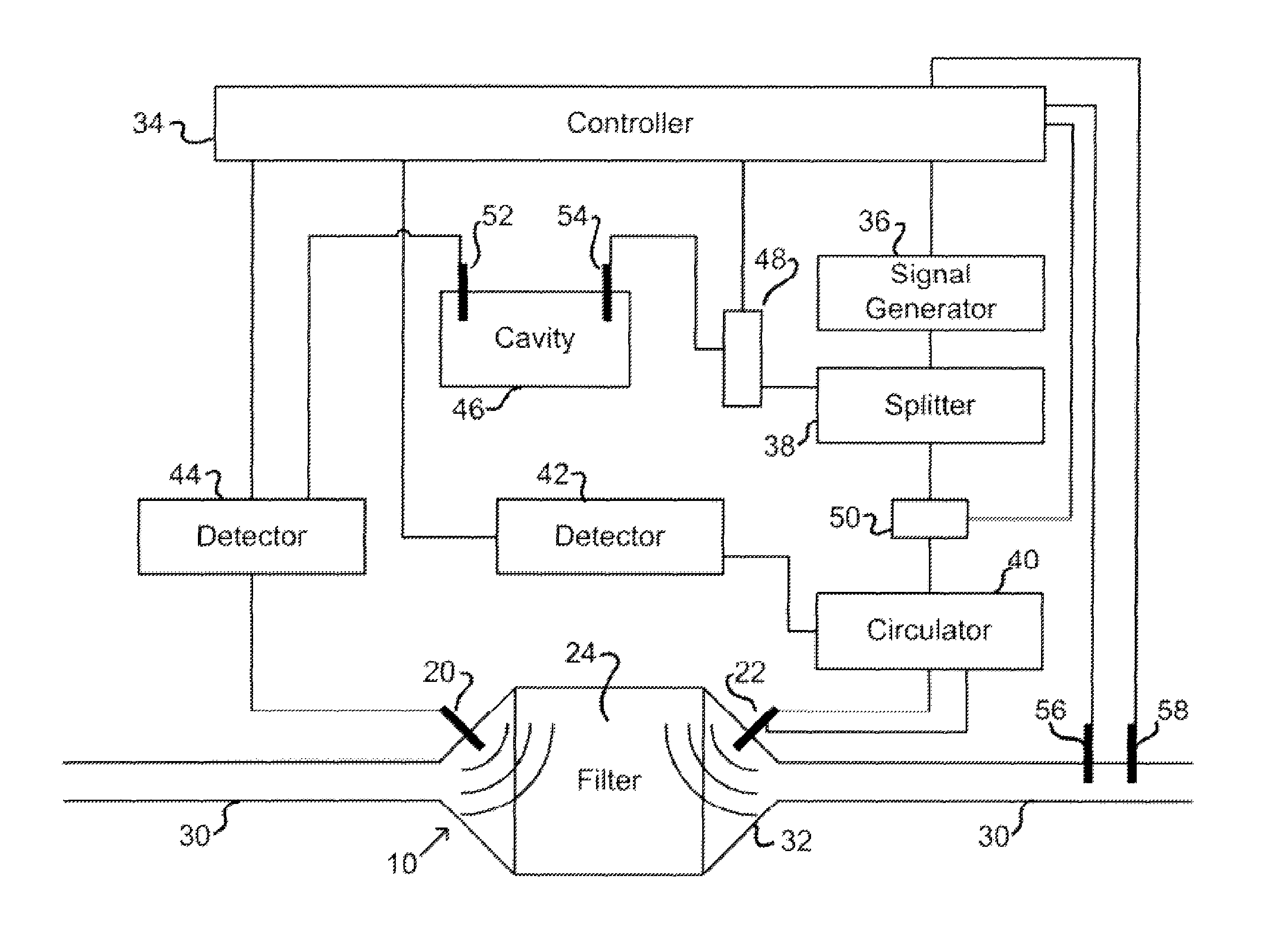
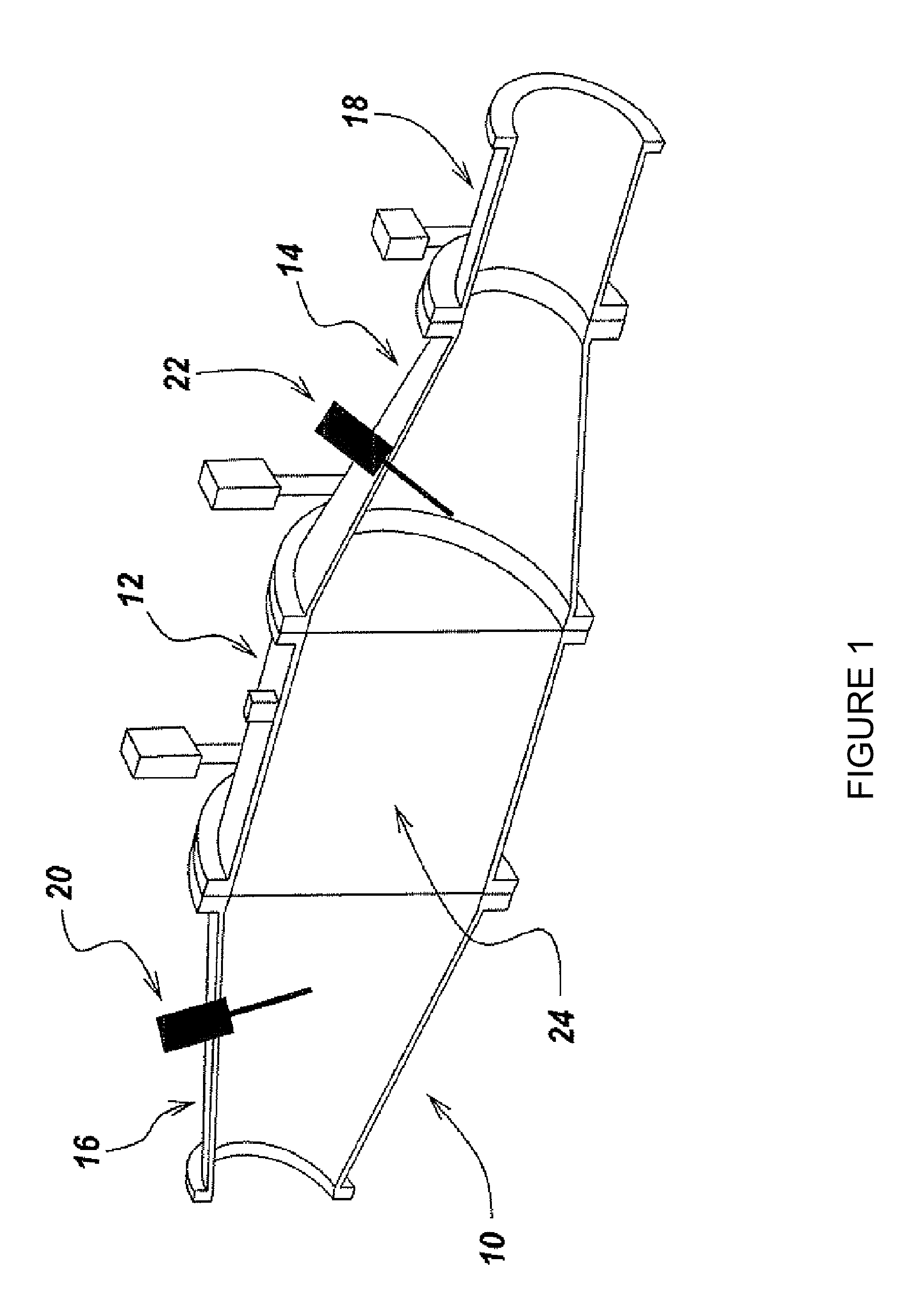
[0023]A system and method for determining loading of a filter having a first dielectric constant with a material having a different dielectric constant, is disclosed. The filter is contained within a metallic container forming a microwave cavity, and microwave or RF energy is created within the cavity and changes in the cavity microwave response are monitored. The changes in cavity microwave response are related to filter loading. In a preferred embodiment, the microwave energy includes multiple cavity modes thereby allowing determination of spatial distribution of the contaminant material loading.
[0028]When two antennas or waveguides are used, they may be located on opposite sides of the filter or on the same side of the filter. In one embodiment, the antennas and waveguides may be located on the downstream side of the filter to prevent contamination.

Problems solved by technology

(a) Prior Art systems are unable to monitor the spatial distribution of material accumulated in the filter.
Further, non-uniform flow conditions may also result in non-uniform material accumulation.
Locally high soot loads cannot be detected by systems which are not capable of measuring material distribution in the filter.
(c) Previous microwave- and RF-based filter loading systems cannot simultaneously detect both soot and ash accumulation in the filter over all exhaust conditions.
(e) These systems do not detect malfunctions or failures of individual components, such as sensors, for example, that may be required for correct operation of the filter.
(g) Previous filter load monitoring systems fail to communicate with existing engine and exhaust sensors to provide feedback control capabilities useful to modify engine operation to optimize the combined engine and after-treatment system performance.

Method used


Image

  • System and method for measuring retentate in filters
  • System and method for measuring retentate in filters
  • System and method for measuring retentate in filters

Examples


Embodiment Construction

[0043]The present invention is based on the recognition that microwaves can be used to determine the status of loading of traps or filters. The loading may be soot, particulates, ash or any solid / liquid. In addition to determining the total amount of loading, the microwave system to be described herein is useful in determining the distribution of the loading throughout the filter. The microwave sensing used in this invention can be inexpensive, as inexpensive oscillators and detectors in the frequency range of interest are commercially available.

[0044]In the case of a diesel particulate filter, the particulates are made from soot and other organic compounds (solid and / or liquid), and ash. For the purposes of this disclosure, the combination of carbon and organic compounds and will be referred to, for simplicity, as soot. Those of skill in the art will recognize that soot and organic compounds are removed through regeneration but ash loading will remain.

[0045]In addition, although th...


PUM

PropertyMeasurementUnit
dielectric constantaaaaaaaaaa
sizeaaaaaaaaaa
volumeaaaaaaaaaa

Abstract

A system and method for determining loading of a filter having a first dielectric constant with a material having a different dielectric constant, is disclosed. The filter is contained within a metallic container forming a microwave cavity, and microwave or RF energy is created within the cavity and changes in the cavity microwave response are monitored. The changes in cavity microwave response are related to filter loading. In a preferred embodiment, the microwave energy includes multiple cavity modes thereby allowing determination of spatial distribution of the contaminant material loading. In one embodiment, the microwave cavity response includes a shift in frequency of a resonant mode. Alternatively, the microwave cavity response includes a shift in quality factor Q of a resonant mode. The microwave cavity response may include a shift in amplitude or peak width of the microwave's signal at resonance.

Description

[0001]This application is a continuation-in-part of U.S. patent application Ser. No. 11 / 741,832 filed Apr. 30, 2007 now U.S. Pat. No. 7,679,374, which claims the benefit of U.S. Provisional Patent Application 60 / 746,081, filed May 1, 2006, the disclosures of which are herein incorporated by reference in their entireties.[0002]This application claims the benefit of U.S. Provisional Patent Application Ser. No. 61 / 110,965, filed Nov. 3, 2008, the disclosure of which is herein incorporated by reference in its entirety.BACKGROUND[0003]This invention relates to determination of contaminant material loading on a filter and more particularly to the use of radio frequencies to determine loading.[0004]In many realms, there is a need for accurate sensing of the amount of material that has been captured by a filter. An example is the need to determine loading of air filters in HVAC systems, filter bag houses used in industrial applications, and even filters used with liquids, and the like.[0005...

Claims


Application Information

Patent Timeline
Patent Type & Authority Patents(United States)
IPC IPC(8): G01R27/04G01R27/32
CPCB01D46/0086F01N9/002G01R27/04F01N2370/22F01N2550/04F01N2560/12F01N2560/14F01N2900/1606F01N2900/1611Y02T10/47G01N22/00Y02T10/40
Inventor BROMBERG, LESLIESAPPOK, ALEXANDERKOERT, PETERPARKER, RONALD
Owner FILTER SENSING TECH
Why Eureka
Try Eureka