Superconducting quick switch

a superconducting, quick technology, applied in the direction of superconducting magnets/coils, magnets, magnetic bodies, etc., can solve the problems of excessive heating in the cryogen environment, reducing the resistance in the magnet coil to negligible levels,

Active Publication Date: 2013-02-26
QUANTUM DESIGN
View PDF38 Cites 69 Cited by
  • Summary
  • Abstract
  • Description
  • Claims
  • Application Information

AI Technical Summary

Problems solved by technology

The extreme cold reduces the resistance in the magnet coils to negligible levels.
Two, it must have a high enough resistance in its normal state such that current flow through the switch during ramp-up is negligible so that excessive heating in the cryogen environment is not produced.
One of the challenges in designing a superconducting switch is to balance the conflicting requirements of minimizing transition time between a superconducting state and a resistive state, and the need for low heat output to minimize cryogen boil-off.

Method used


Image

  • Superconducting quick switch
  • Superconducting quick switch
  • Superconducting quick switch

Examples


Embodiment Construction

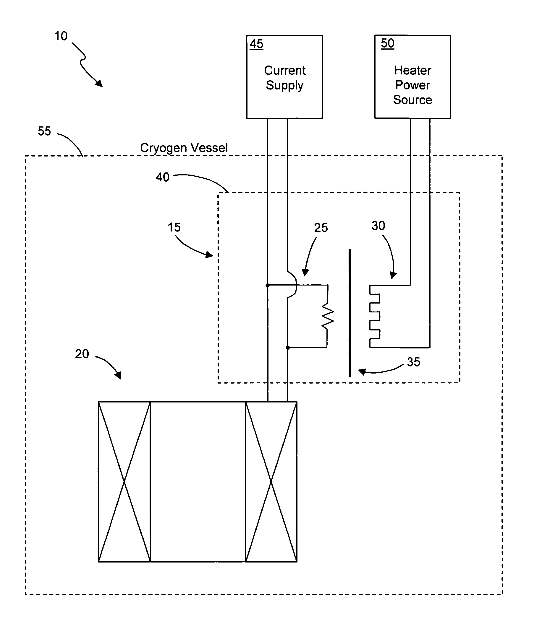
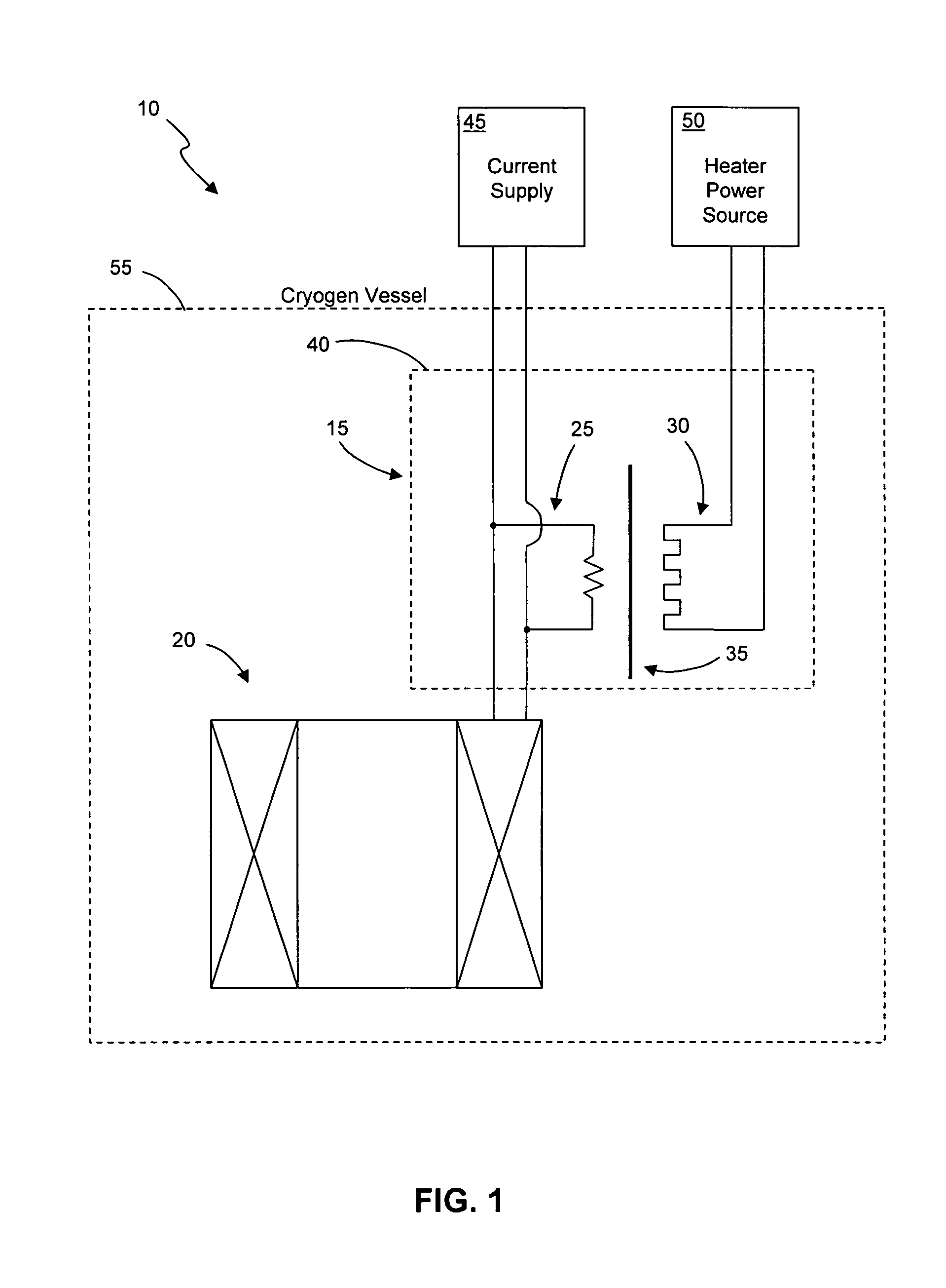
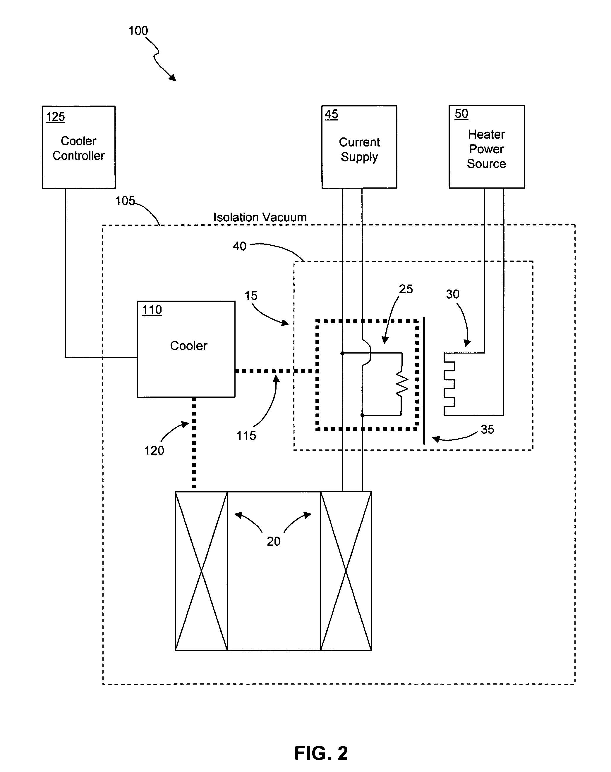
[0014]In the following detailed description, reference is made to the accompanying drawing figures which form a part hereof, and which show by way of illustration specific embodiments of the invention. It is to be understood by those of ordinary skill in this technological field that other embodiments may be utilized, and structural, electrical, as well as procedural changes may be made without departing from the scope of the present invention. As a matter of convenience, various components of a magnet system and associated superconducting switch will be described using exemplary materials, sizes, shapes, and dimensions. However, the present invention is not limited to the stated examples and other configurations are possible and within the teachings of the present disclosure.

[0015]Referring now to FIG. 1, an electrical schematic diagram of an embodiment of a magnet system of the present invention is shown. In particular, magnet system 10 is shown having switch assembly 15 and super...


PUM

PropertyMeasurementUnit
diameteraaaaaaaaaa
diameteraaaaaaaaaa
diameteraaaaaaaaaa

Abstract

A magnet system for generating a magnetic field may include a superconducting magnet, a switch, and a heater element thermally coupled to the switch. The superconducting magnet is structured to generate magnetic fields, and the switch includes a non-inductive superconducting current carrying path connected in parallel to the superconducting magnet. In general, the switch is structured to only carry a level of current that is a portion of the current required to obtain a full field by the superconducting magnet.

Description

BACKGROUND OF THE INVENTION[0001]1. Field of the Invention[0002]The present invention relates generally to magnet systems, and in particular to a non-persistent switch for use with a superconducting magnet.[0003]2. Discussion of the Related Art[0004]As is well known, a magnet can be made superconducting by placing it in an extremely cold environment, such as by enclosing it in a cryostat or pressure vessel containing liquid helium or other cryogen. The extreme cold reduces the resistance in the magnet coils to negligible levels. After the power source that is initially connected to the coil is removed, the current will continue to flow through the magnet coils relatively unimpeded by the negligible resistance, thereby maintaining a magnetic field.[0005]To maintain current flow in the magnet coils after removal of power, it is typically necessary to complete the electric circuit within the cryogenic environment with a superconducting switch that is connected in parallel with the powe...

Claims


Application Information

Patent Timeline
Patent Type & Authority Patents(United States)
IPC IPC(8): H01F1/00H01F6/00H01F7/00
CPCH01F6/008H01L39/20H10N60/355
Inventor DIEDERICHS, JOSTAMANN, ANDREASSIMMONDS, MICHAEL B.
Owner QUANTUM DESIGN
Why Eureka
Try Eureka