
Transmitting a signal from a power amplifier

a power amplifier and signal technology, applied in the direction of digital transmission, limiting the amplitude of digital/coded signals, baseband system details, etc., can solve the problems of increasing adjacent channel leakage and distortion, high computational complexity of the scheme, and incurring a high processing burden in terms of processing cycles

Active Publication Date: 2013-02-26
ICERA INC
View PDF8 Cites 1 Cited by
  • Summary
  • Abstract
  • Description
  • Claims
  • Application Information

AI Technical Summary

Benefits of technology

The patent describes a method, computer program product, and transmission system for limiting peak-to-average power of a signal transmitted from a power amplifier. This is accomplished by applying a pulse-shape filter to the signal, and then using a set of predictor filters to approximate the application of the pulse-shape filter based on different filter coefficients. The method also includes generating an indicator of amplitude for each predictor filter, selecting the indicator with the highest amplitude, and generating a modifier based on the selected indicator to limit the signal prior to applying the pulse-shape filter. The technical effect of this patent is to reduce peak-to-average power of the signal, which improves the efficiency of the power amplifier and reduces the likelihood of distortion.

Problems solved by technology

Generally speaking, increased non-linearity in the radio frequency power amplifier (PA) leads to increased adjacent channel leakage and distortion.
However, this scheme has a high computational complexity and hence incurs a high processing burden in terms of processing cycles.

Method used


Image

  • Transmitting a signal from a power amplifier
  • Transmitting a signal from a power amplifier
  • Transmitting a signal from a power amplifier

Examples


Embodiment Construction

[0028]The disclosure recognizes the benefit of a practical peak-to-average ratio (PAR) power limiter which can operate with reduced computational complexity compared to conventional PAR power limiters but with little or no ACLR degradation. Additionally, the disclosure also recognizes the benefit of operating such a power limiter on the uplink while still meeting the strict ACLM and EVM restrictions.

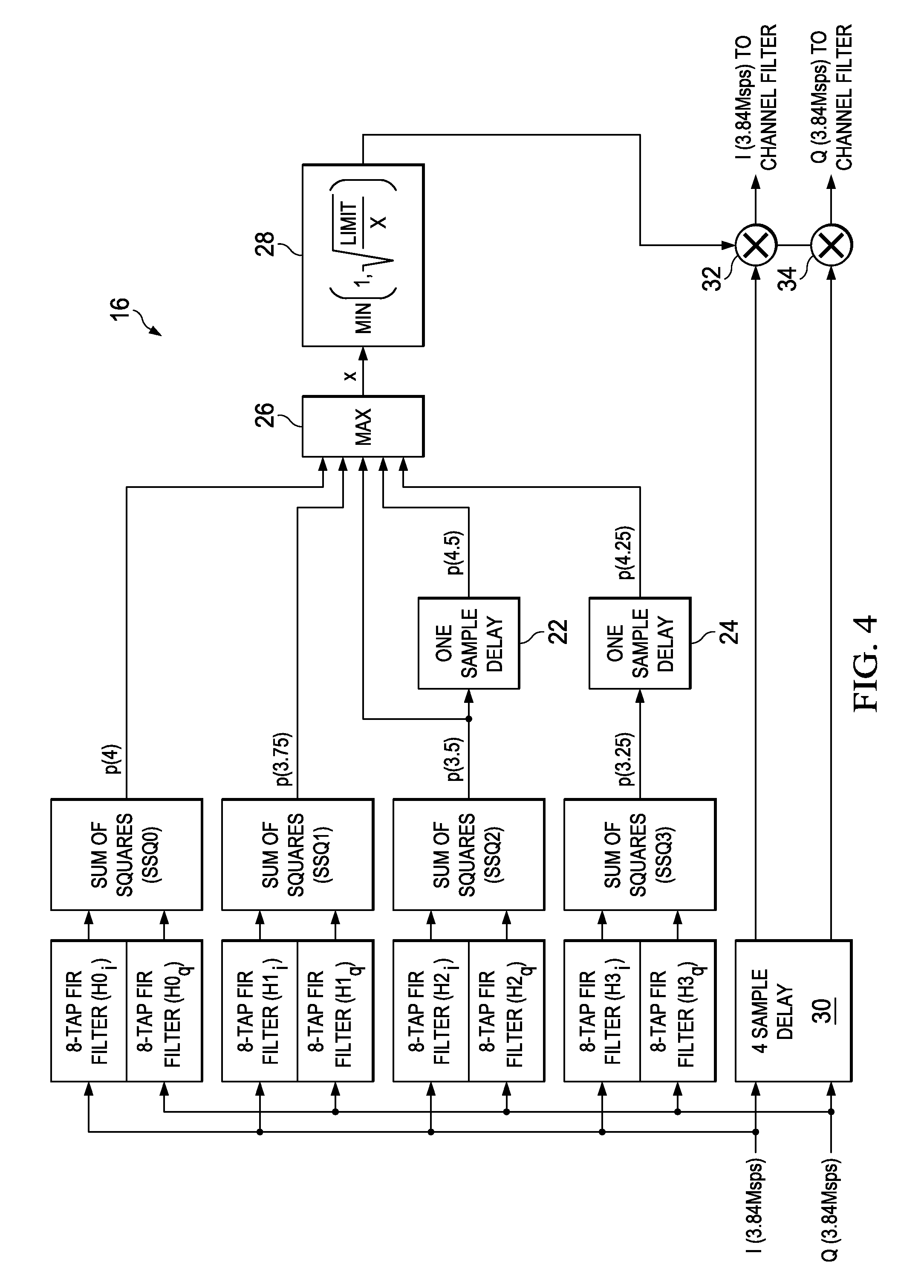
[0029]As mentioned, Marsili proposes a pre-processing scheme for limiting the peak-to-average power ratio (PAR). However, the Marsili scheme is complicated to implement, and hence incurs a high processing burden. Particularly, the technique in Marsili requires calculating the amplitude of four interpolated signals (requiring four square root operations), determining four sets of complex additive correction terms (ei=1 . . . 4), filtering those terms to time align them with the original signal value, and finally, selecting the maximum of the four filtered complex correction terms for subt...


PUM


Abstract

A method for limiting peak-to-average power of a signal transmitted from a power amplifier. The method comprises: applying a pulse-shape filter to a first signal, thereby generating a second signal being a filtered version of the first signal; and outputting the second signal for transmission from a power amplifier. The method further comprises: applying each of a plurality of predictor filters to a respective instance of the first signal, each predictor filter approximating the application of the pulse-shape filter to the first signal based on a different respective set of filter coefficients, and each thereby generating a respective third signal. The method also further comprises determining an indicator of amplitude of each of the third signals, selecting the indicator corresponding to the largest of those amplitudes, generating a modifier based on the selected indicator, and using the modifier to limit the first signal prior to applying the pulse-shape filter.

Description

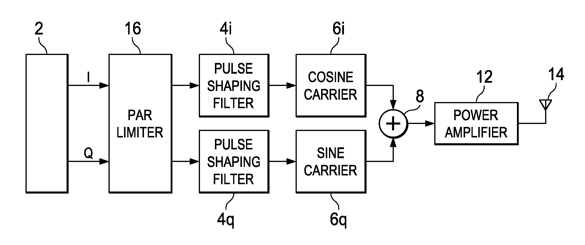
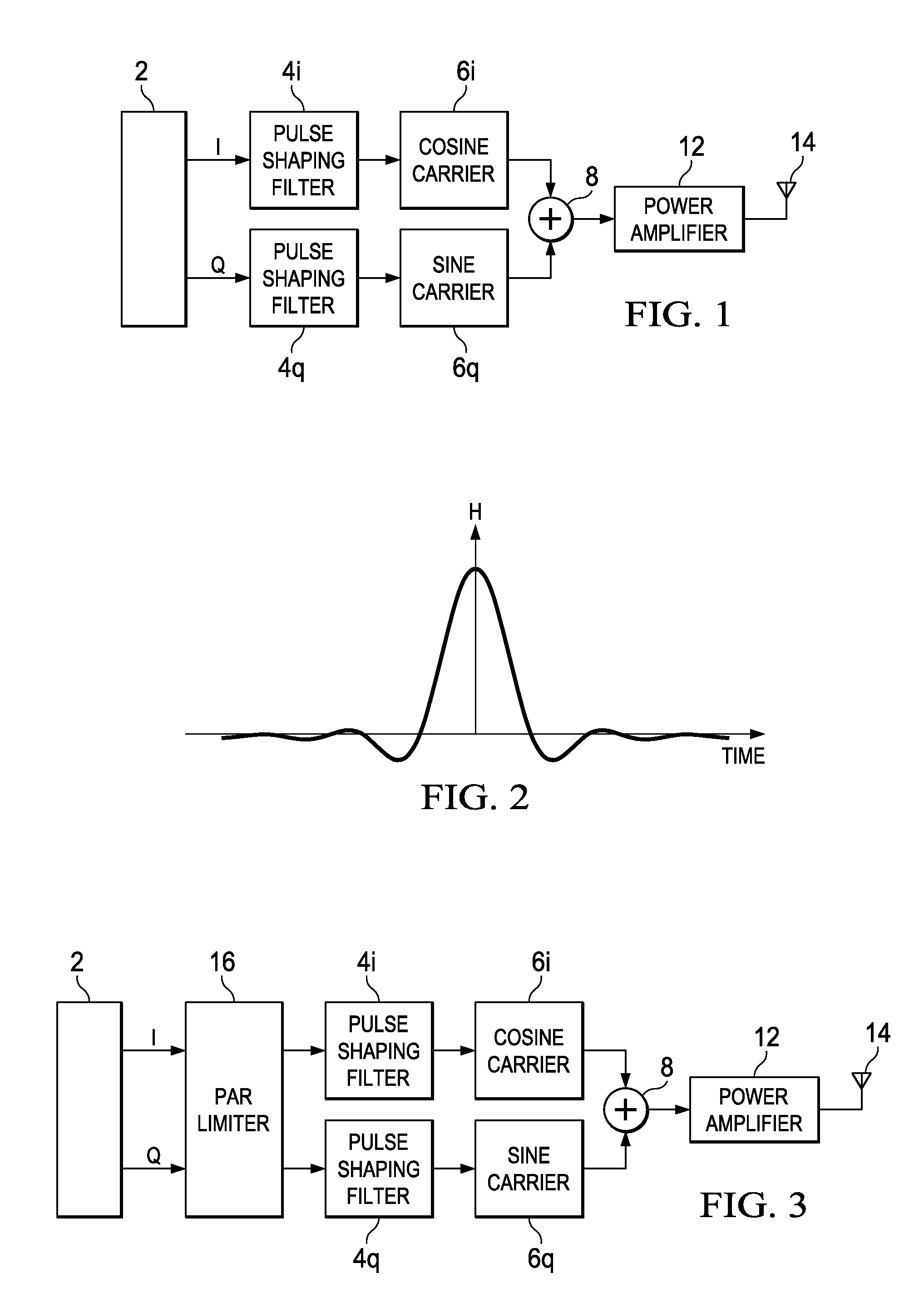
CROSS-REFERENCE TO RELATED APPLICATION[0001]This application claims the benefit of GB Application No. 1014659.5 filed on Sep. 3, 2010, entitled “TRANSMITTING A SIGNAL FROM A POWER AMPLIFIER”, commonly assigned with this application and incorporated herein by reference.TECHNICAL FIELD[0002]The present disclosure relates to limiting peak-to-average power of a signal transmitted from a power amplifier, e.g. for transmission over a wireless cellular network.BACKGROUND[0003]FIG. 1 is a schematic block diagram of a wireless transmitter. The transmitter comprises an initial data processing stage 2 arranged to generate data on an in-phase (I) branch and a quadrature branch (Q). In operation, the data processing stage 2 begins by generating digital data for one or more channels to be modulated for transmission via the I branch and one or more channels to be modulated for transmission via the Q branch.[0004]The data on each channel is initially generated in binary form. As a first step of the...

Claims


Application Information

Patent Timeline
Patent Type & Authority Patents(United States)
IPC IPC(8): H04K1/02H04L25/03H04L25/49
CPCH04B1/707H04L27/367H03F2200/336H03F2200/451H03F2201/3206H04L27/2614H03F1/3241H03G11/008H04L27/3411
Inventor FELIX, STEPHENALLPRESS, STEVE
Owner ICERA INC
Learn More